Key takeaways
- Two axes add directional measurements; the measurement program determines how they are used.
- Inclination correction addresses target orientation, rather than every source of measurement error.
- Range, target position and the exact document revision belong with any specification.
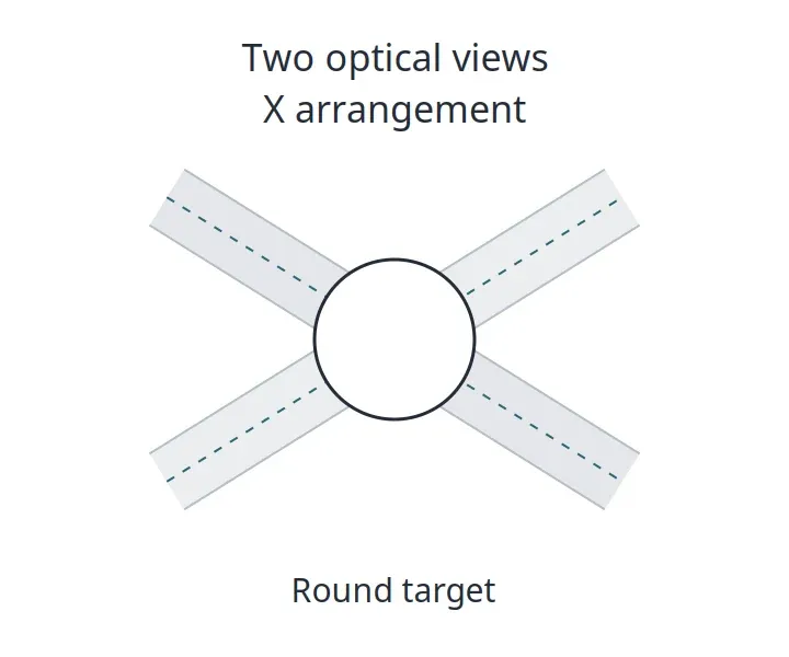
Confusing a tilted target with a changing diameter can waste a quality investigation. An X arrangement adds a second optical view; each ODC2700’s diameter program can already correct inclination in its own view.
For a profileGAUGE C.ODC specs search, start with what the two axes measure and which conditions accompany the numbers. Micro-Epsilon describes two preassembled optoCONTROL ODC2700 micrometers in an X. This guide explains that arrangement for engineers assessing wire, tube or round-stock inspection, compares it with a single directional measurement, and identifies document discrepancies to resolve before integration. The comparison is based on public information, not a production test. It sits in our component guides as an instrumentation explanation.
What was reported, and what does the manufacturer confirm?
Instrumentation Monthly published its profileGAUGE report on October 6, 2026. Micro-Epsilon’s product page confirms the X arrangement, simultaneous measurements on two axes and active inclination correction. The date of the media report is a reporting date, not proof of the first release or US availability of the instrument.
| Record | Date or status | What it supplies |
|---|---|---|
| Instrumentation Monthly report | October 6, 2026 | Manufacturer-origin description and headline specifications |
| Manufacturer product page | Checked October 8, 2026 | Arrangement, programs, interfaces and inclination-correction statement |
| Linked catalog and setup guide | Checked October 8, 2026; version applicability to be confirmed | Model table, footnotes and operating-program instructions |
Read a product announcement and an operating document for different purposes. The former tells you why to look; the latter tells you what to configure and what conditions to reproduce. Our sources methodology follows that distinction rather than treating repeated coverage as independent validation.
Takeaway: Use the news date to locate the report, then use the applicable manufacturer documents to assess the instrument.
How do two optical views address target tilt and center position?
An optical micrometer evaluates a target’s projected edges in a light field. A single directional reading describes that view; adding a second axis provides another directional view of the target. Micro-Epsilon’s setup guide says the Diameter preset compensates in real time when the object is tilted relative to the measuring plane.
The X refers to the arrangement of the two optical paths, not to two contact micrometers touching the material. The manufacturer’s catalog describes the system for cylindrical objects such as tubes, wires and round stock. Its simultaneous views support diameter and center-axis evaluation, with the selected preset and output settings governing the result.
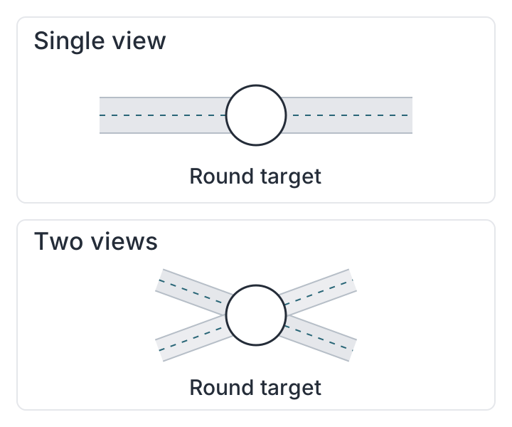
Inclination correction is not a capability created merely by adding the second axis. Micro-Epsilon’s single-ODC2700 page describes detecting target orientation and using integrated processing to adjust the dimension in the diameter programs. The second sensor adds a measurement direction. The manufacturer’s documents do not disclose a two-axis fusion algorithm that this guide can reproduce.
For center-position assessment on moving material, also verify the acquisition state. The system permits synchronous and asynchronous operation. Setup-guide sections 3.4–3.5 instruct users to select the required outputs, such as diameter or center point, for each sensor and describe synchronizing the two receivers; the manufacturer recommends synchronization. Pair the two-axis data consistently, retain the encoder association where used, and identify the control or evaluation system that processes the values. A simultaneous position claim needs that configured data path.
The implication for a line investigation is practical: distinguish a change in the target’s orientation or position from a change in the dimension being monitored. Save those quantities separately where the chosen output configuration supports them. The engineering checklist offers the same general discipline of keeping operating conditions with a measured specification.
This is not a universal geometric reconstruction. Two observed directions do not establish every dimension of an arbitrary cross-section. Define the measurand—the quantity the inspection is intended to report—before choosing a preset.
Takeaway: Decide whether you need diameter, directional width or center position before configuring the two-axis outputs.
When is the second axis relevant to a line evaluation?
A second direction is relevant when the inspection task includes orientation, center position or dimensions in more than one view. It is not automatically necessary for every width measurement. Compare the information required by the acceptance decision with the information available from the proposed program, then prepare a representative sample evaluation.
| Inspection question | Single ODC2700, one directional view | X arrangement described by Micro-Epsilon |
|---|---|---|
| A dimension in one defined view | Produces a reading for that view | Adds another directional reading |
| Position in two measurement directions | Another observation would be needed | Paired axes support evaluation when the required synchronized outputs are configured |
| Tilted cylindrical target | Diameter programs already include inclination correction | Adds another direction; verify each sensor’s diameter preset |
| Full contour of an arbitrary shape | One projection is insufficient evidence | Two directions alone do not establish a full reconstruction |
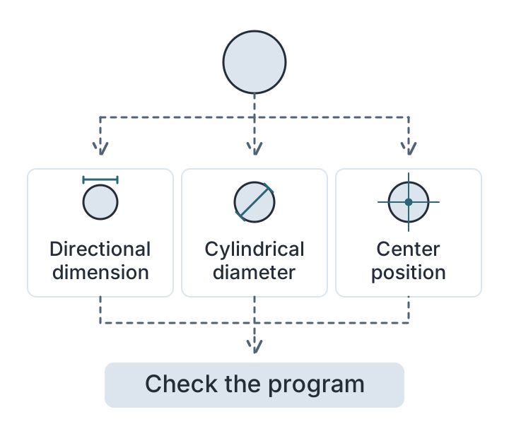
For wire-line quality engineers, record the diameter interval, expected motion and the point where the gauge would observe the material. For integration engineers, record the required output and how it will be associated with the line position. This is an editorial evaluation checklist, not a manufacturer acceptance procedure.
The idea of relating a quantity to the task also appears in phase-noise measurement: a headline value loses its meaning when its measurement conditions are detached. A sensor resolution field deserves the same care.
Takeaway: Add a second axis for a defined information need, then demonstrate that need with the intended material and motion.
Which published numbers need their conditions restored?
The linked catalog distinguishes target-size and repeatability values by range, and its measuring-rate statement differs from the product page. Those differences make version and configuration checks part of the assessment. The following is a document-reading record, not a consolidated performance specification or a claim about an installed instrument.
| Field | Published record checked October 8, 2026 | Meaning for the evaluation |
|---|---|---|
| Minimum target size, C.ODC-10/2 family | Catalog: 0.05 mm, with 0.03 mm in brackets | Footnote ties the bracketed value to the middle of the measuring range |
| Minimum target size, C.ODC-40/2 family | Catalog: 0.3 mm, with 0.1 mm in brackets | The smaller-range claim does not transfer to this family |
| Resolution | Catalog: 10 nm at the digital interface | A resolution field is not an overall accuracy result |
| Linearity, 10 mm family | Catalog: ≤0.5 µm in field 1; ≤1 µm in field 2; ≤2.5 µm in field 3 | Specified Z intervals are ±0.5 mm, ±1.5 mm and ±2.5 mm respectively |
| Linearity, 40 mm family | Catalog: ≤1 µm in field 1; ≤3 µm in field 2 | Specified Z intervals are ±2.5 mm and ±10 mm respectively |
| Repeatability | Catalog: ≤0.03 µm for the 10 mm family; ≤0.1 µm for the 40 mm family | Footnote requires specified averaging, timing and a temperature-stabilized environment |
| Inclination-corrected rate | Product page: up to 5 kHz; linked catalog: up to 15,000 measurements/s | Confirm which hardware, firmware and document revision apply |
The catalog repeatability footnote specifies diameter measurements with a 95% confidence interval, averaging 1,024 values over five minutes in a temperature-stabilized environment after 45 minutes of warm-up. That is not a stated repeatability result for every individual sample in a moving-line installation. The catalog’s linearity footnotes use a 2 mm testing pin at a target-to-receiver measurement distance of 150 mm; the listed field boundaries determine which value applies. Footnote 6 attaches the stated averaging, confidence and environmental conditions to both linearity and repeatability. These are catalog conditions, with supply-version applicability still to be confirmed, rather than an overall accuracy guarantee.
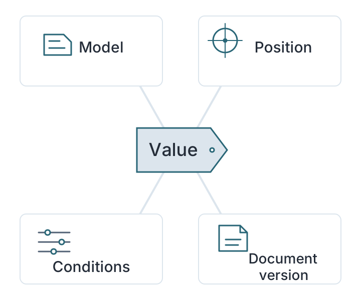
Common mistake: Putting a “30 µm minimum” and “10 nm accuracy” into a purchase specification. The former depends on the catalog’s model and position; the latter misnames resolution.
Keep the applicable evidence with the requirement using the engineering comparison checklist, and preserve its provenance using the sourcing and quality framework.
Takeaway: Copy the value and its footnote together, and resolve the rate discrepancy before making a throughput requirement.
What should US engineers do next, and what stays unresolved?
Technical evaluation can start from the public documentation now; purchasing and installation dates require confirmation for the selected variant. Create a question record that links each issue to a document or test. A supplier answer should identify the configuration it covers instead of simply repeating the headline specifications.
| Open item | Who can resolve it | Requested evidence |
|---|---|---|
| 5 kHz versus catalog 15 kHz statement | Manufacturer technical support | Applicable hardware/firmware and dated specification |
| Transparent target and actual line motion | Application engineer and line quality owner | Representative-target evaluation with defined measurand |
| Protection accessories and optical conditions | Manufacturer application contact | Configuration-specific instructions and evaluation conditions |
| Trigger, output and position association | Controls integrator | Each sensor’s preset and outputs, synchronization state, two-axis data pairing and encoder association |
| US availability and delivery | US supply channel | Written confirmation for the exact variant; date to be confirmed |
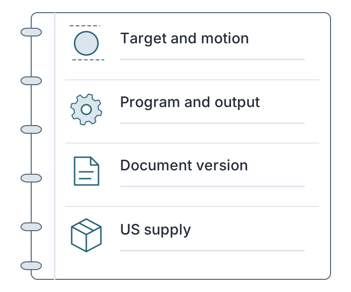
The site’s publication scope explains how independently organized manufacturer information supports a technical review. The fact-checking policy provides a way to report a specification discrepancy after publication.
Takeaway: Begin with a technical question record; set the introduction date after configuration and supply are confirmed.
When this does not apply
This article does not establish acceptance limits, guarantee compensation for all motion or certify performance on transparent materials. A non-cylindrical section, an uncharacterized target or a different optical program needs its own assessment. Nor does an optical dimensional result establish electrical performance, cleanliness or material identity.
The editorial policy describes how the site handles the limits of source-based explanations. An application evaluation still needs the selected instrument’s instructions and representative test conditions.
Takeaway: Keep the dimensional measurement within its defined task and use separate evidence for the other acceptance requirements.
Method and sources
The arrangement and preset explanation come from Micro-Epsilon’s product page, catalog excerpt and setup guide. The media report is a manufacturer-origin account, not a second performance test. The numeric table preserves the disagreement between the live page and the linked catalog instead of selecting an unsupported combined specification. The documents were checked on October 8, 2026; this review did not establish which version is supplied in the US.
Further reading
- Engineering guides — Keep measurement conditions attached to a specification.
- Phase-noise explanation — See why a measured quantity and its conditions belong together.
- Sources methodology — Distinguish published claims from independent verification.
Frequently asked questions
What is an optical micrometer?
In the optoCONTROL 2700 system, an object interrupts an LED light field and the receiver evaluates its projected edges. It is a non-contact measurement principle. The measurement program determines whether those edges are used for a diameter, a gap or another supported quantity.
How accurate are optical micrometers?
There is no single accuracy value for the category. Check the model's linearity conditions, target position and measurement uncertainty for the application. The linked profileGAUGE catalog reports resolution and repeatability separately; neither should be substituted for an overall accuracy claim.
What does μm stand for?
The symbol μm denotes micrometres, also spelled micrometers in US English. Record the unit beside each dimensional field when copying the catalog; its tables use both millimetres and micrometres. Keep those dimensions separate from measurement rates expressed in kHz.
Sources
- profileGAUGE C.ODC product page — Micro-Epsilon Accessed October 8, 2026.
- profileGAUGE catalog excerpt, printed pages 26–27 — Micro-Epsilon Accessed October 8, 2026.
- profileGAUGE C.ODC setup guide, diameter preset — Micro-Epsilon Accessed October 8, 2026.
- optoCONTROL 2700 optical micrometer — Micro-Epsilon Accessed October 8, 2026.
- Meet profileGAUGE C.ODC — Instrumentation Monthly Accessed October 8, 2026.