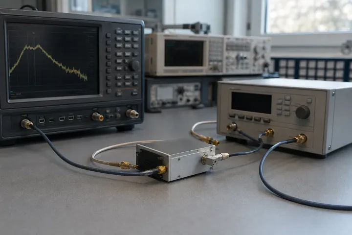
Direct answer
Yes. Keep service calibration, internal alignment and external-chain verification separate; each supports a different part of the reported result.
An alignment success message can leave a measurement team with the wrong kind of evidence. A successful internal alignment does not by itself establish traceability for the complete measurement. Before accepting a result, separate the instrument’s service record, its current operating corrections and the connected test chain. This check sheet accompanies the RF engineering guides.
The three-column calibration check sheet
Use this sheet at the start of a run. These are separate evidence checks; a pass in one column does not fill a missing record in another. For the units and offsets on the eventual plot, see the live phase-noise guide.
| Instrument service calibration | Run-specific setup and alignment | External-system verification |
|---|---|---|
| Identify the unit, installed options, certificate and calibrated functions. | Identify the operating mode, firmware and applicable manual procedure. | Identify every cable, adapter, buffer, reference and frequency-conversion stage used. |
| Check that the report covers the quantities and operating range needed for this job. | Complete the prescribed warm-up and alignment; save the outcome and warnings. | Check delivered signal level, loading and the noise contribution of added hardware. |
| Record calibration date, applicable interval, reported uncertainty and limitations. | Record carrier, offset span, input level, attenuation, reference and correlation settings. | Retain a connection sketch, relevant component evidence and the verification result. |
| Missing coverage: resolve with the calibration provider before claiming it. | Failed or stale alignment: follow the instrument’s troubleshooting instructions. | Uncharacterized chain: leave its uncertainty unresolved; do not invent a correction. |
The table is a proposed working record, not a substitute for a manufacturer’s calibration procedure. A missing value should remain Unknown / verify on the unit until its supporting record is available.
What internal alignment actually establishes
The FSWP version 17 manual, section 3.14, calls for self-alignment after environmental temperature changes or a firmware update. It requires operating temperature first and no signal connected to the RF input during alignment. Section 12.1 describes the stored correction record and its outcomes, including a restricted result and failure. Save the actual outcome rather than recording only that the command ran.
Those are FSWP instructions. Read the equivalent section for another analyzer; do not copy a warm-up duration or menu sequence from a different model.
Even the word calibration can name a narrower function. Keysight’s E5052B User Calibration applies correction data to power readings; in phase-noise mode, the listed corrected quantity is carrier signal level. That function’s name does not establish that every phase-noise error source has been verified.
The connected chain still needs its own check
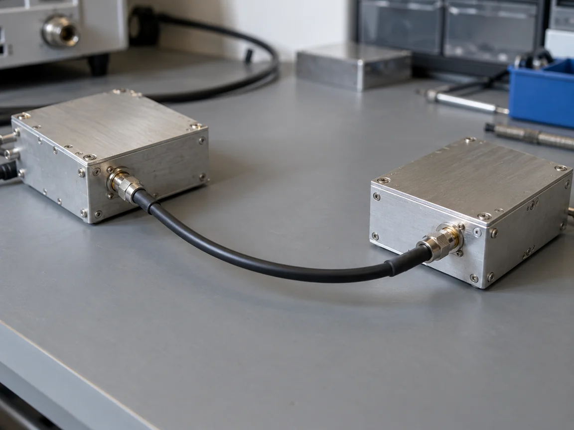
SiTime AN10062, sections 4.1–4.3, explains how weak input signals and added amplifiers or probes can limit the measurement. It also discusses how the analyzer’s load can affect an oscillator output. A calibrated analyzer therefore cannot settle every question about a signal delivered through extra hardware.
Our recommendation is to keep a connection sketch with the run. If a buffer or converter changes, treat its evidence as a new check rather than carrying forward an old setup approval. The frequency-converter guide helps identify translation stages to include in that sketch.
R&S application note 1EF95, sections 4 and 4.1, describes phase-noise traceability through underlying RF quantities, including linearity and power. Its uncertainty model includes reference noise, unwanted signals, mismatch, repeatability, correlated hardware limits, bandwidth and the RF cable. Use that as a reason to ask what a calibration report covers, not as certification of another unit.
More averaging is also a separate decision. SiTime section 5.4 describes cross-correlation as reducing uncorrelated channel noise at the cost of measurement time. It does not supply missing calibration records. If the result remains limited by the measurement system, record that limitation rather than presenting the displayed curve as an unrestricted DUT result.
How often should service calibration be repeated?
There is no universal annual rule to apply to every phase-noise analyzer. NIST’s interval guidance says the choice depends on required accuracy, contractual or regulatory obligations, device stability and environment. It recommends measurement assurance and historical data to establish and refine intervals when external requirements do not decide them. Retain both incoming and post-calibration results so the interval can be reviewed.
Start with the exact unit’s manufacturer recommendation and your quality-system obligations. Document the chosen interval and its basis. Do not interpret an internal-alignment reminder as the service-calibration due date.

Keep a record that supports the reported result
NIST’s traceability FAQ, sections 5.1.1 and 5.2.1, attaches traceability to a measurement result. Supporting it requires a documented calibration chain and associated uncertainty. An instrument certificate alone is insufficient to make every later result traceable.
Copy this record into the run notes. Blank entries are intentional fields to complete, not example specifications.
Identify an external synthesized reference with its reference and lock arrangement. If the report also includes jitter, carry the integration limits into the log-spaced phase-noise integration record.
| Record field | Entry for this run |
|---|---|
| Analyzer model, serial number, options and firmware | |
| Certificate ID, scope, date and interval basis | |
| Carrier frequency and input level at analyzer | |
| Offset range and reported phase-noise points | |
| Reference source, attenuation and correlation settings | |
| Warm-up condition, alignment date and outcome | |
| External hardware and connection-sketch reference | |
| Verification method, result and acceptance criterion | |
| Measurement uncertainty, applicable conditions and source | |
| Operator, saved data file and unresolved limitations |
For exploratory work, retain the same setup notes even when the result will not carry a traceability claim. Before releasing a specification or acceptance result, resolve missing coverage and uncertainty with the responsible measurement team. The other engineering guides can help interpret the signal; this record documents why the measurement can be accepted.
Method and sources
Updated 15 October 2026. This guide combines the opened manufacturer documents and NIST guidance listed below. The three-column sheet is our editorial synthesis. Procedures remain specific to the model, configuration and quality requirements; no laboratory performance, calibration service or measured noise floor is claimed here.
Sources
- FSWP User Manual, version 17, sections 3.14 and 12.1 — Rohde & Schwarz Accessed October 15, 2026.
- 1EF95: Measurement Uncertainty Analysis and Traceability for Phase Noise — Rohde & Schwarz Accessed October 15, 2026.
- AN10062: Phase Noise Measurement Guide for Oscillators — SiTime Accessed October 15, 2026.
- E5052B User Calibration — Keysight Accessed October 15, 2026.
- Recommended Calibration Interval — NIST Accessed October 15, 2026.
- Metrological Traceability: Frequently Asked Questions and NIST Policy — NIST Accessed October 15, 2026.