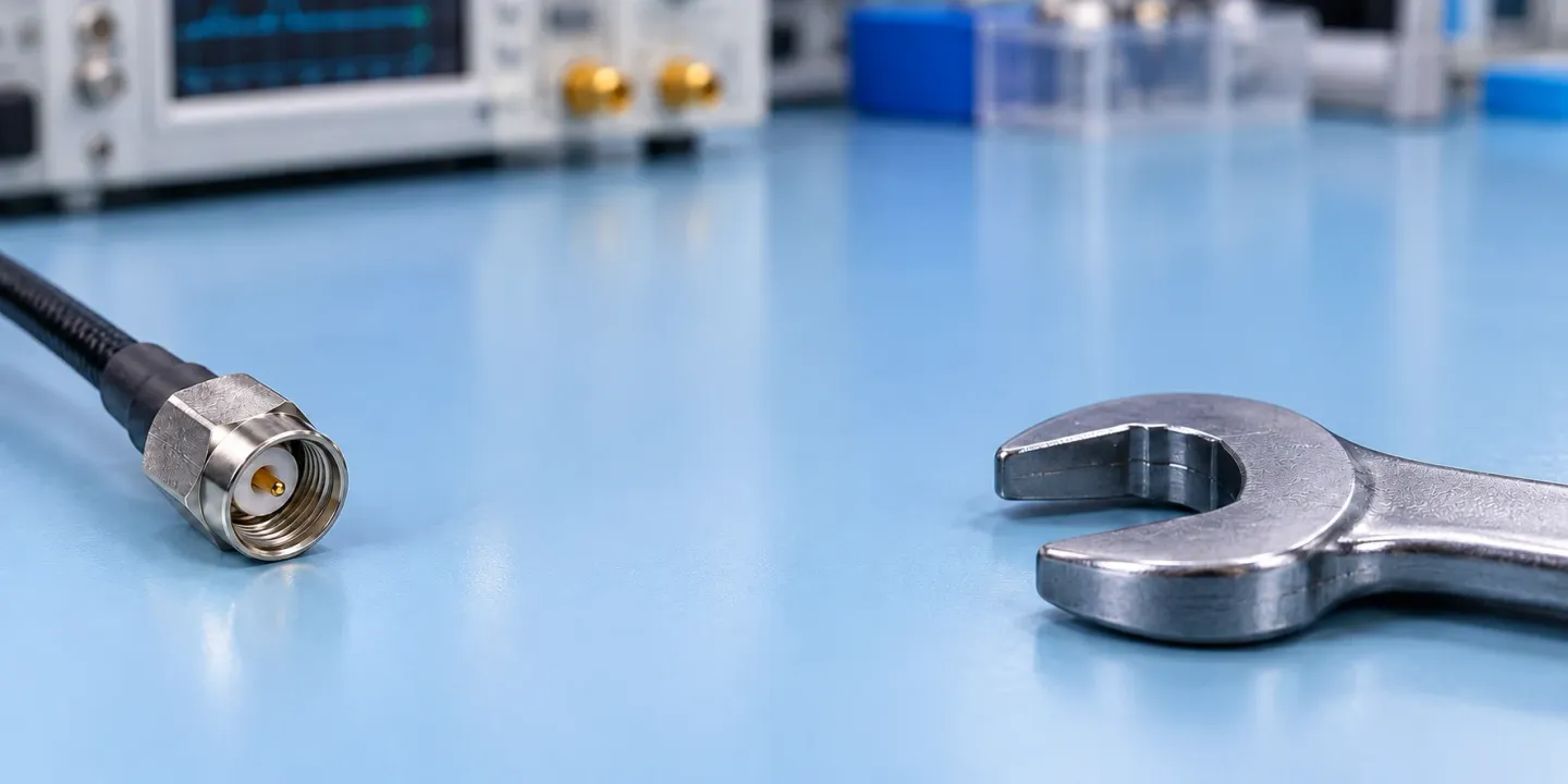
Use the instrument user and service guides for specific torque recommendations. Hold the anti-torque hex stationary with a wrench while tightening the coupling nut until the torque wrench releases.
Use this bench guide to choose the setting, prepare the mating faces, and record the disposition of a suspect connection. For related component guides, browse Components.
Choose the SMA torque wrench setting for the connection
Start with the applicable product and mating instruction. Keep the connector material and mating orientation alongside the setting in your inspection record.
For Taoglas brass SMA connectors, the torque wrench value should be 0.57N-m (5in-lb). For Taoglas Stainless Steel SMA connectors, a torque value of 0.9N-m (8in-lb) should be used.
For the Keysight FlexDCA mating procedure, a 56 N-cm torque wrench should be used to connect male SMA connectors to either 3.5-mm or 2.92-mm connectors. For the Keysight FlexDCA mating procedure, a 90 N-cm torque wrench should be used to connect male 3.5-mm or male 2.92-mm connectors to mating female connectors.
Inspect and hand-mate before applying the wrench
Visual inspection and, if necessary, cleaning should be done every time a connection is made. Visually check the coupling nut threads and mating face for foreign objects. The coupling nut should turn freely relative to the anti-torque hex.
Align connector center lines before mating where applicable. The cable should not rotate during hand mating.
A coupling nut that is difficult to turn during mating may be cross-threaded. If the coupling nut is difficult to turn during mating, stop and determine the reason before proceeding.
Which wrench flats stay still?
For the Taoglas tightening procedure, use the following sequence:
-
Place the torque wrench on the coupling nut.
-
Hold the anti-torque hex stationary with a wrench while tightening the coupling nut until the torque wrench releases.
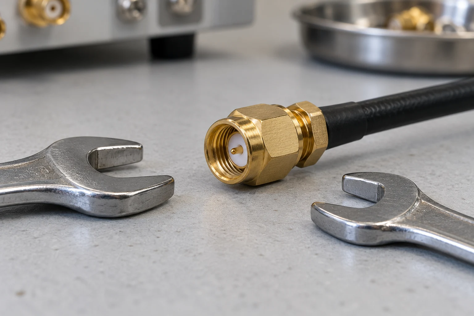
For the Keysight precision-connector wrench procedure:
-
Position the torque wrench and holding wrench within 90° of each other before applying force.
-
Hold the torque wrench lightly at the end of its handle.
-
Apply force perpendicular to the torque-wrench handle.
-
Stop at the initial torque-wrench break point.
Use the RF connector pin depth gauge before mating
The Keysight connector-care gauging sequence starts here:
Gauge a connector or adapter before first use. Gauge when visual inspection or electrical performance suggests an out-of-range interface.
Before gauging any connector, the mechanical specifications provided with that connector or device should be checked. Select the correct gauge for the device under test.
Anritsu specifies the cleanliness check: A pin depth gauge must be checked for cleanliness before each use.
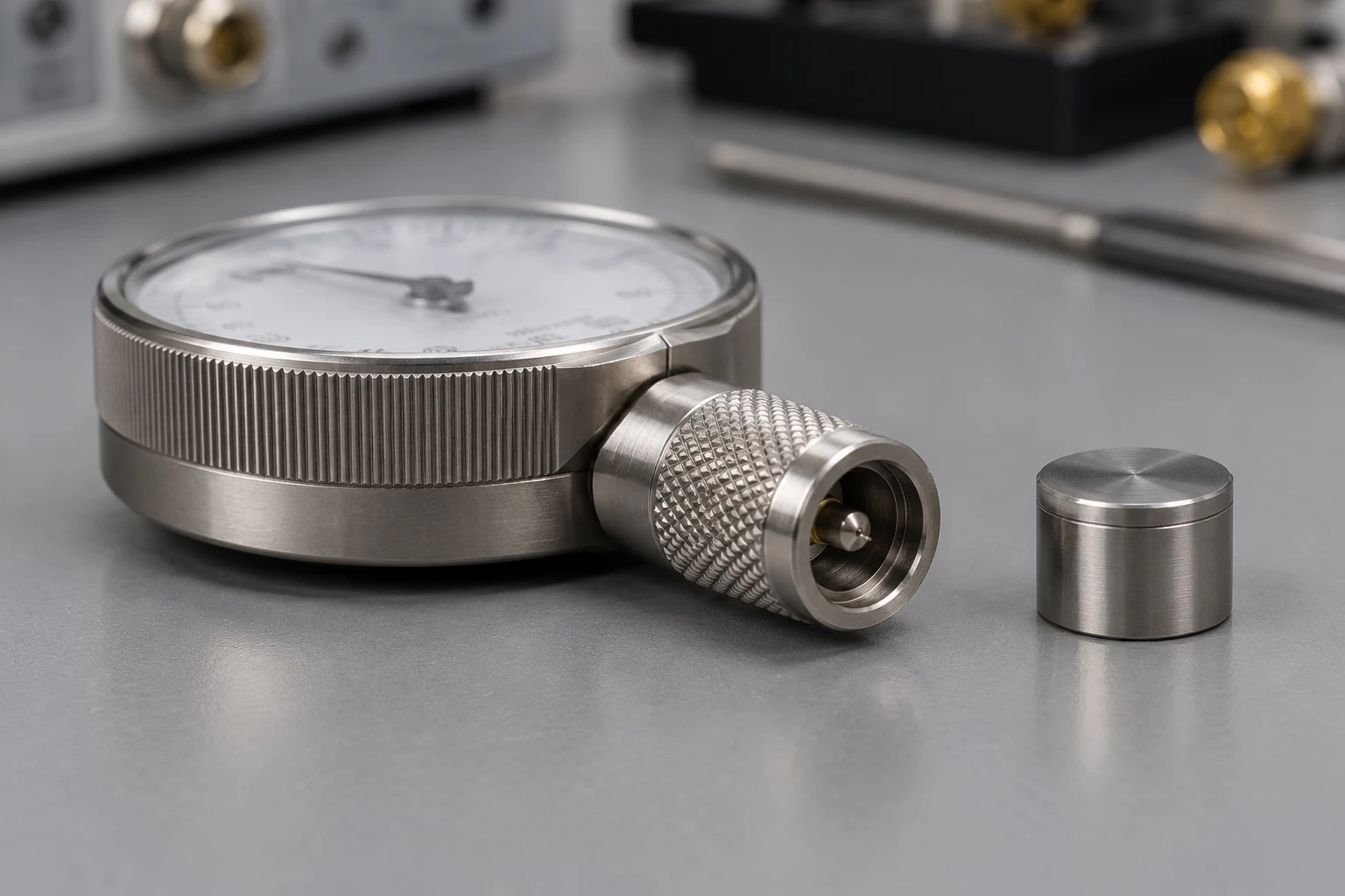
Continue with the Keysight gauging procedure:
-
Gauges should be zeroed before each set of measurements.
-
Compare the recession or protrusion reading against the device specifications.
-
For maximum accuracy, measure at least three times and average the readings.
-
Rotate the gauge a quarter-turn after each measurement to reduce variation.
Read recession and protrusion against the device specification
Negative pin depth means the center conductor is recessed below the outer-conductor mating plane. Positive pin depth means the center conductor projects forward from the reference plane.
Out-of-tolerance positive pin depth can buckle female center-conductor fingers. Out-of-tolerance negative pin depth can cause poor return loss.
If the gauge indicates excessive protrusion or recession, the connector should be marked for disposal or sent out for repair.
Investigate center-conductor and coaxial connector mating damage
An overlong male SMA pin can smash or break the fingers of a precision 3.5 mm female connector.
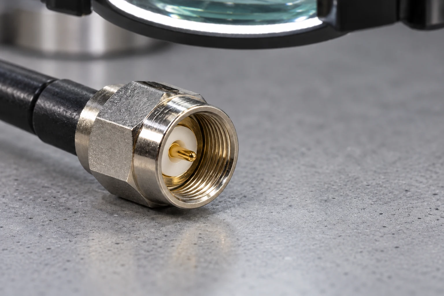
For cable-assembly handling, Gore identifies the following damage mechanisms:
-
Allowing the body to rotate with the tightening nut will wear away plating and score both the outer interface rim and the pin of both connectors.
-
Depending on connector type, over-torque can cause recessed or protruding pins.
-
Depending on connector type, over-torque can cause recessed or protruding dielectrics.
-
Depending on connector type, over-torque can mushroom pin shoulders.
Remove defective connectors from the mating sequence
Any connector that has obvious defects should be discarded. An assembly with bent pins, damaged dielectric, thread damage or recessed or protruding pins should be replaced before its further use results in equipment damage. Inspect the mating connectors as well.
Keep a connector inspection record
Copy these blank fields into your bench record:
- Connector and mating-device identity
- Applicable torque instruction and material
- Moving coupling nut and stationary holding flats
- Mating-face and thread observations
- Gauge identity, reference and zero check
- Pin-depth readings and device acceptance limits
- Prescribed torque and wrench identification
- Disposition and mating-connector inspection
For the next measurement task, use the RF-to-IF isolation measurement guide. Keep this connector checklist with your setup notes.
Continue your bench documentation with RF, IF and LO terminology, frequency-converter specifications, and radar component selection.
Sources
-
Anritsu — RF and Microwave Connector Care
-
Gore — Microwave/RF Assemblies Care and Handling
-
Keysight — 11878A Operating and Service Manual
-
Keysight — FlexDCA 3.5 mm Precision Connectors
-
Keysight — Connector Care
-
Keysight — PXI VNA Connector Care
-
Taoglas — SMA Connector Torque Guide