Direct answer
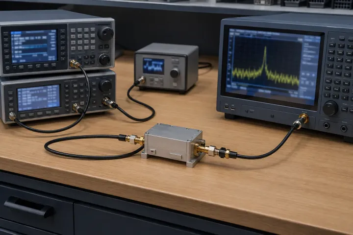
An omitted RF-to-IF isolation figure fails a comparison when one supplier used normal LO drive and another used a high-power RF surrogate. Mini-Circuits measures that path with normal LO drive and RF power in the linear operating range, on a spectrum analyzer. Marki Microwave's 8 February 2013 note drives the RF port at high power, the same way it measures LO-to-IF isolation. Copper Mountain Technologies' 19 April 2018 demonstration generates the LO and measures feedthrough at the IF, with the LO at 501 MHz. Fill the record on this page before you treat two numbers as the same leakage.
Key takeaways
- Mini-Circuits measures RF-to-IF isolation with normal LO drive and RF power in the linear range, on a spectrum analyzer.
- Marki's 8 February 2013 note uses a high-power RF input for RF-to-IF isolation and shows the M1-0412LA changing with measurement power.
- Copper Mountain's 19 April 2018 demonstration generates the LO and measures IF feedthrough, with the LO at 501 MHz.
- Power at the wanted IF is conversion. Power at the original RF frequency is feedthrough. Keep the two readings in separate rows.
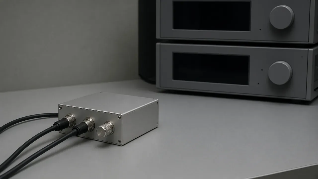
An omitted RF-to-IF isolation figure fails a comparison when one supplier used normal LO drive and another used a high-power RF surrogate. Mini-Circuits measures that path with normal LO drive and with the RF input in the linear operating range. The reading is taken on a spectrum analyzer so the fundamental stands apart from the other lines.
This sheet sits with the other RF engineering guides. It is the record you fill when a datasheet prints LO-to-RF and LO-to-IF isolation and leaves RF-to-IF isolation empty. Port names are the ones in RF, IF and LO explained. A module that already includes amplifiers and filters is specified on the frequency converter guide. Moving a signal onto another pin is a separate check, on the mixer port-swap sheet.
What a blank RF-to-IF line leaves unknown
Mini-Circuits AN00-009 states the company’s own practice: normally only the LO isolations are specified, because the RF signal power is much lower than the LO drive level, so RF leakage is usually not a limiting performance factor. The same note defines the two LO figures it does publish. LO-to-RF isolation is the amount the LO drive power is attenuated when it is measured at the RF port, with the IF port terminated in 50 ohms. LO-to-IF isolation is the amount the LO drive power is attenuated when it is measured at the IF port, with the RF port terminated in 50 ohms.
Marki Microwave’s note of 8 February 2013 ranks the three paths for a balanced mixer. LO-to-RF isolation matters most, because the LO tends to sit close to the RF (the IF is usually the low frequency) and then falls inside the band of the following parts, in an upconversion or a downconversion. LO-to-IF isolation is the worst of the three. The LO can contaminate wideband IF circuitry, and LO power reflected from the IF circuitry can raise conversion loss. RF-to-IF isolation is the smaller problem in that note, because the LO is the strongest signal in the system.
Copper Mountain Technologies’ note of 19 April 2018 lists six names: LO-RF and RF-LO, LO-IF and IF-LO, RF-IF and IF-RF. It calls the pairs highly reciprocal and says standard practice is to measure LO-RF, LO-IF, and RF-IF. It also says LO-RF and LO-IF matter most to systems engineers, because LO power is normally much greater than RF or IF power, and that design engineers may pay closer attention to RF-IF isolation because it plays a larger role in conversion loss.
AN00-009 adds one general figure for Mini-Circuits’ own parts: at the highest frequency of operation, its double-balanced mixers provide isolation of 30 dB. The note ties that falloff to transformer unbalance, lead inductance, and capacitive unbalance between diodes. Use that 30 dB figure for Mini-Circuits double-balanced mixers at the highest frequency of operation in AN00-009.
The archived question that prompted this page asks why RF/IF isolation is typically left off a mixer datasheet. The thread body was absent from the archive used here, so the page stops at the two published reasons above. What you can still settle is which conditions a number has to carry before it counts as the leakage in your converter.
Takeaway: A blank RF-to-IF cell means the leakage under your LO level, your RF level, and your analyzer frequency is still unknown. Mini-Circuits’ 30 dB sentence stays on Mini-Circuits’ double-balanced mixers.
Three published setups, side by side
The three notes describe RF-to-IF leakage with different stimuli. A number from one column is a different measurement from a number in the next column. Where the archived text is silent, the cell says so.
| Record | Mini-Circuits AN00-009, RF-to-IF | Marki, 8 February 2013, RF-to-IF | Copper Mountain, 19 April 2018, RF-to-IF |
|---|---|---|---|
| Stimulus | RF power in the linear operating range. The paragraph gives no dBm value for that range. Elsewhere, the note says the IF-to-RF power ratio starts to change by about 0.1 dB when the RF is within about 10 dB of the LO drive, and it defines the 1 dB compression point as the RF level where conversion loss is 1 dB greater than at low RF power. | A high-power RF input, measured the same way as LO-to-IF isolation. The note says mixer diodes stay off until the rated drive, around +10 to +13 dBm for a typical double-balanced L-diode mixer, and that some VNAs cannot produce that power across the whole band. | The LO is generated and feedthrough is measured at the IF port. The archived text does not state the RF stimulus level. |
| LO state and level | Normal LO drive. The note’s level examples, for the mixer type named, are +7 dBm for a Level 7 mixer, +17 dBm for Level 17, and +23 dBm for Level 23. The RF-to-IF paragraph says “normal LO drive” and does not repeat one of those numbers. Conversion loss changes slightly when the LO leaves the recommended level. | The note says normal operation uses a strong LO. It does not state whether that LO stays on during the high-power RF measurement. | LO generated. For the isolation measurements, the LO was set to 501 MHz so it would not interfere with the measurement data. The isolation section does not state the LO power. |
| Analyzer frequency | A spectrum analyzer replaces the RF voltmeter. The power at the fundamental frequency of measurement is separated from the other components. Broadband use judges the harmonics. Narrowband use keeps the fundamental. | For a working conversion, isolation is the LO input power divided by the output power at the LO frequency at the RF or IF port, or the same ratio as a subtraction in dBm. The RF-to-IF sentence says to measure it the same way as LO-to-IF isolation and does not restate a tune frequency. | Feedthrough at the IF port. The note does not state the analyzer frequency. It sets the LO to 501 MHz so the LO would not interfere with the measurement data. |
| Terminations | All factory mixer measurements use a 50-ohm broadband system. The LO-to-RF and LO-to-IF paragraph puts a 50-ohm termination on the port that is not being read, and a pad between the generator and the mixer. The RF-to-IF paragraph does not restate a termination or a pad. | The note does not state the termination. | LO-to-IF: the RF port is terminated with a load. LO-to-RF: the IF port is terminated with a load. The RF-to-IF sentence does not name a termination. |
| Reference plane | The note does not name a reference plane beyond the 50-ohm system. | The note does not state a reference plane. | Isolation measurements used a standard SOLT 2-port calibration. The VSWR section of the same note says the powers stated there are at the VNA ports, and the power entering the mixer is 0.1 to 0.2 dB lower because of the cable. The isolation section does not repeat that offset. |
| Part the note actually shows | The setups are described for Level 7 mixers as conceptual diagrams. Production testing, the note says, uses integrated automated equipment. | Graphs of an M1-0412LA, one at a measurement power of -5 dBm and one at more than 10 dBm. The note states that increasing the input power by 20 dB in this case can lead to an isolation improvement of 20 dB or better. The archived text does not print the curve values. | Mini-Circuits ZX05-1L-S+ as the mixer under test, on a Copper Mountain Technologies 804/1 VNA. The demonstration kept the IF bandwidth at 100 Hz unless a figure stated otherwise. The isolation section does not state a different bandwidth. |
Marki presents the high-power RF input as a surrogate that should track the isolation you would see in operation, because the LO and RF ports of a mixer are generally interchangeable. The same note is also the source of the M1-0412LA comparison: isolation on that part changed between a measurement power of -5 dBm and a measurement power of more than 10 dBm. Those two sentences travel together. A high-power surrogate and a low-power VNA sweep are different rows even when both come from the same application note.
Takeaway: Copy a number only with the column it came from. A Mini-Circuits linear-range reading, a Marki high-power RF reading, and the Copper Mountain 501 MHz LO setup are three measurements.
Conversion power and RF-frequency feedthrough
AN00-009 defines conversion loss as the ratio of RF input power to IF single-sideband output power, as a positive number in dB, in a 50-ohm system, at the LO level specified for that mixer. The conversion-loss setup puts a low-pass filter ahead of the power meter so every response other than the desired IF is rejected. LO leakage has no effect on that reading, because it never reaches the meter. A spectrum analyzer can replace the power meter, and then the filter can be omitted, because the analyzer selects a frequency.
The RF-to-IF isolation setup uses the spectrum analyzer for a different selection. The power at the fundamental frequency of measurement has to be distinguishable from the other lines. That fundamental is the leakage frequency of the stimulus. The desired IF is the converted product the low-pass filter was keeping for the conversion-loss test. The two readings answer different questions, and the record below gives each its own row.
Marki’s working-conversion formula is the leakage form: LO input power minus the output power at the LO frequency, in dBm. Copper Mountain writes the same relation for LO-to-RF isolation as LO power in minus RF power out, with the powers in dBm and the isolation in dB. Its conversion-loss formula is separate: RF power minus IF power, in dBm, giving conversion loss in dB.
Takeaway: Write the frequency the analyzer was tuned to. A number at the wanted IF is conversion power. A number at the original RF frequency, or at the LO frequency, is feedthrough.
The record to copy
Use one sheet per part number and per datasheet revision. Leave a cell empty when the note you were given does not state it. A class sentence from the table above can sit in the margin. It does not fill the cell. Confirm the marking against that revision before you rely on a bit of the table; the obsolete RF component sourcing guide covers marking and revision checks.
| Group | Field | Entry |
|---|---|---|
| Identity | Part number, datasheet revision, date of the number | |
| Path | Which pair: RF to IF, IF to RF, LO to IF, IF to LO, LO to RF, or RF to LO | |
| Stimulus | Port, frequency, and level | |
| LO | On or off, frequency, and level | |
| Analyzer | Instrument, and the frequency it was tuned to | |
| Which product | Power at the wanted IF, or power at the original RF frequency, or power at the LO frequency | |
| Terminations | What is on each port that is not the stimulus and not the analyzer | |
| Reference plane | Instrument port or mixer connector, and any stated cable offset | |
| Convention | Mini-Circuits linear-range LO drive, Marki high-power RF surrogate, Copper Mountain LO-on feedthrough, or another setup the supplier names | |
| Result | The isolation in dB, with the unit, or empty |
Takeaway: Six condition rows plus the result. An empty cell stays empty until the datasheet, or a measurement made under those conditions, fills it.
When this does not apply
Copper Mountain’s vector-mixer-calibration section sets requirements for the second mixer used as the calibration mixer. The mixer under test keeps its own RF-to-IF cell. That calibration mixer needs at least 20 dB of isolation between LO and RF and between LO and IF. Its RF power is operated in the linear region, which the note describes as typically 30 dB below the LO power. The LO power at calibration has to equal the LO power in operation, and it has to equal the LO power of the mixer under test. Conversion loss of that calibration mixer has to be under 10 dB. Those sentences stay on the calibration mixer.
Marki’s range of about +10 to +13 dBm is the drive at which a typical double-balanced L-diode mixer’s diodes turn on, in the 8 February 2013 note. Mini-Circuits’ +7 dBm, +17 dBm, and +23 dBm are the recommended LO levels for Level 7, Level 17, and Level 23 mixers. Each figure stays with the mixer class the note named.
The M1-0412LA graphs and the ZX05-1L-S+ demonstration are one part each. Curve values that the archived text does not print are omitted here. Rewiring RF, IF, and LO pins belongs on the mixer port-swap sheet. An amplified converter stays on the converter guide.
Takeaway: Keep the 20 dB figure on Copper Mountain’s calibration mixer, and keep the 30 dB figure on Mini-Circuits’ double-balanced mixers at the highest operating frequency.
Method and sources
The comparison is compiled from public application notes archived on 11 October 2026. AN00-009 supplies Mini-Circuits’ definitions, the 30 dB sentence, the Level 7, 17, and 23 LO examples, and the RF-to-IF measurement paragraph. The Mini-Circuits blog post of 1 May 2015 repeats that measurement paragraph and is the shorter of the two. Marki’s 8 February 2013 note supplies the path ranking, the LO-frequency formula, the diode drive range, the M1-0412LA powers, and the high-power RF surrogate. Copper Mountain’s 19 April 2018 note supplies the six path names, the 501 MHz LO, the SOLT calibration, the ZX05-1L-S+ demonstration, the cable offset in the VSWR section, and the calibration-mixer requirements.
The everything RF article of 1 August 2018 was opened. Its isolation number has no part number, no LO level, and no analyzer frequency, so this page leaves that number out.
No mixer was measured for this page. Corrections follow our editorial policy.
Frequently asked questions
Why is RF-to-IF isolation often omitted from an RF mixer datasheet?
Mini-Circuits states its own practice in AN00-009: normally only the LO isolations are specified, because the RF signal power is much lower than the LO drive level, so RF leakage is usually not a limiting performance factor. Copper Mountain Technologies says LO-RF and LO-IF matter most to systems engineers because LO power is normally much greater than the RF or IF power, while design engineers may pay closer attention to RF-IF isolation because of its role in conversion loss. Neither sentence fills a blank cell on another vendor's datasheet. Record the conditions in the table on this page.
How do you measure RF-to-IF isolation when the datasheet leaves it blank?
Mini-Circuits applies normal LO drive and RF power in the linear operating range, then reads a spectrum analyzer so the fundamental stands apart from the other lines. Marki Microwave's 8 February 2013 note applies a high-power RF input, measured the same way as LO-to-IF isolation, and says that surrogate should track operating performance because the LO and RF ports are generally interchangeable. Write the LO state and the analyzer frequency on the record before you keep either number.
Sources
- AN00-009: Mixers: Terms Defined, and Measuring Performance — Mini-Circuits Accessed October 11, 2026.
- How to Measure Isolations (8 February 2013) — Marki Microwave Accessed October 11, 2026.
- RF Mixer Characterization (19 April 2018) — Copper Mountain Technologies Accessed October 11, 2026.
- Understanding RF Mixer Isolation (1 August 2018) — everything RF Accessed October 11, 2026.