Direct answer
On a bare passive diode mixer, Marki Microwave treats the three ports as physically interchangeable, and the performance changes. Recheck the passband, DC path, rated LO drive, isolation, conversion loss, and spurs on the physical pins before you keep the swap. An active mixer, an IQ mixer, or an amplified converter does not inherit that diode rule. The part datasheet sets drive and damage limits.
Key takeaways
- A bare passive diode mixer can be rewired, and the published numbers still belong to the original pin assignment.
- After any exchange, copy passband, DC path, rated LO drive, isolation, conversion loss, and spurs from that datasheet revision.
- Analog Devices does not guarantee an RF and LO exchange on the HMC554 or the HMC773. Measure spurs if that is why you flipped a passive diode mixer.
- Active mixers, IQ mixers, and amplified converters stay on their own datasheet limits. The diode table does not cover them.
Putting the local oscillator on the wrong mixer pin can raise conversion loss, send more leakage out of the intermediate-frequency port, and exceed the drive level the datasheet states for a different pin. Fill the two tables on this page before the board is reworked.
The sheet sits with the other signal chain guides. It decides which port exchange a topology still supports, and which six specifications you copy again from the datasheet. The three port names are the ones in RF, IF and LO explained. Conversion direction is decided on upconverter vs downconverter. Image placement, running a module backwards, and IF-reflection checks stay on the other guides.
Which swap the topology allows
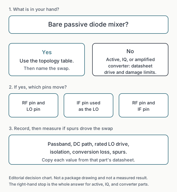
Marki Microwave’s FAQ on LO and RF interchange says that, in a passive diode mixer, the three ports are physically interchangeable and performance will change significantly. Any port can be the LO. Either remaining port can be the signal port. The same note says the mixer is specified for its lowest conversion loss and its broadest bandwidth in the standard wiring, and that these mixers are optimized for L-R isolation (LO to RF). That is the boundary of the table below. It describes a bare passive diode mixer.
Mini-Circuits’ topology guide of 7 March 2022 is the source for how the diode networks differ. The guide draws the circuits with diodes and says the same structural ideas show up in other device technologies. That sentence is about baluns and diode rings. It does not move a drive limit or a damage limit onto an active mixer, an IQ assembly, or a converter.
| Topology | RF pin and LO pin exchanged | IF pin used as the LO | What you copy from the datasheet |
|---|---|---|---|
| Unbalanced, single diode | RF and LO share one diode port in the guide’s drawing. The IF leaves through a tank tuned to the IF. Swapping the two input tones changes which filter must pass which tone. The guide lists no port isolation to exchange. | The tank is tuned to the IF. An LO on that node leaves the circuit the drawing shows. | How the input tones are split, the IF tank band, and the LO level. The guide calls this the lowest LO power of the four diode topologies. |
| Single balanced | The tone on the 180° hybrid port is the one removed from the IF. The guide says that port can be wired as the LO or as the RF. Move the LO off it and the balance no longer removes the LO. The other input still needs the filter. | The drawing suppresses RF at the IF with a capacitor to ground and a low-pass, and it shunts RF chokes to ground between the coupler and the diodes so the diodes do not self-bias at high LO power. An LO on the IF node sees that filter and that DC network. | Which tone is on the 180° port, the IF filter, and the LO level. This type uses the least LO power of the balanced mixers, and more than the single diode. High LO power can self-bias the diodes. The guide’s class note is 20 to 30 dB of LO or RF rejection at the IF. The part datasheet replaces that note. |
| Double balanced, passive diode | Marki: less LO power can be used, with more conversion loss than the standard wiring. The lowest loss and the widest band are specified for the standard wiring. For the HMC554 and the HMC773, Analog Devices says the exchange is not guaranteed. See the worked reply below. | Marki: significant harmonic content appears at the RF and LO ports. | Each physical port’s frequency range, whether the IF node taken from the baluns passes DC, the rated LO drive, the LO level used for the isolation table, conversion loss at that drive, and the spur you care about. The guide says this circuit isolates RF and LO at the IF without a filter, needs more LO power than a single-balanced mixer, has fewer spurs than that circuit, and has less conversion loss than both the single-balanced and the triple-balanced circuits. The ports are sensitive to reactive terminations. |
| Triple balanced, diode | Two hybrids on RF and LO, and one hybrid on the IF. Marki’s passive-diode caveat still says the ports can be exchanged and the performance changes. The IF hybrid means this is a different experiment from turning a double-balanced ring around. | The IF port is a hybrid. Confirm that hybrid’s band before you drive it as an LO. | LO drive, which the guide says is the highest of the four, the wide IF bandwidth the guide describes, isolation, and spur suppression. The guide says spur and intermodulation suppression are stronger than in a double-balanced mixer, and that the circuit is used when the RF and IF bands overlap. Confirm overlap on the datasheet. |
| IQ or image-reject assembly | Two mixers plus a 90° split on the LO. An image-reject or single-sideband version adds a hybrid on the I and Q ports. An inner cell can be one of the diode rows above. The assembly’s port list is not three pins. | I and Q are ports of that structure, not a third pin of one ring. | The IQ datasheet. This table does not assign those ports. |
| Active mixer, or an amplified converter | Outside Marki’s passive-diode sentence. | Outside that sentence. | Recommended drive and damage limits on the labeled pins or connectors. The next section says where the table stops. |
Takeaway: Use a row only when the part in your hand is that bare passive diode topology. A vendor can still refuse to guarantee the swap on one diode part.
What you write down before and after
The permutation table says which exchange is even a candidate. The record below is what you fill for the part number on the board. Class notes tell you which cell to open in the datasheet. They do not fill the cell.
| Record | Designed connection | After the swap you will test | Copy from the datasheet | Class note you can use beside it |
|---|---|---|---|---|
| Passbands | Write the RF, LO, and IF ranges and the conditions on each. | The tone has to fit the physical port it now uses. | The three frequency ranges, with the drive and temperature stated for them. | Marki: the standard wiring is where the lowest conversion loss and the broadest band are specified. Unbalanced and single-balanced drawings in the Mini-Circuits guide put a tank or a low-pass on the IF, so that path stays narrow. |
| DC path | Write coupled, blocked, or choke-to-ground for each pin. | The driver and the next stage see the new pin’s DC network. | Coupling, bias pins, and any absolute maximum DC voltage. | The single-balanced drawing uses RF chokes to ground and an IF low-pass. A driver that cannot hold a DC short fails if it lands on a choke. The double-balanced guide takes the IF from the baluns and does not say that every such node passes DC. Confirm that on the datasheet before you drive the node or bias through it. |
| Rated LO drive | Write the stated LO level and which pin receives it. | The physical pin that now receives the LO still has to accept that drive. | Recommended LO level, and the damage or absolute-maximum rating if the datasheet gives one. | Marki, for a passive diode mixer with LO and RF exchanged: less LO power can be enough, with more conversion loss. That is a direction, not a new rating. For the HMC554 and the HMC773, the 29 September 2015 reply still wanted +13 dBm on the physical LO port for optimal operation, and it did not guarantee the swap. |
| Isolation | Write LO-to-IF, RF-to-IF, and LO-to-RF, with the LO level used for each. | Leakage follows the path the tone now takes. | The isolation table and the LO level it assumes. | For the HMC554 and the HMC773, Analog Devices said to use RF-to-IF isolation for LO leakage at the IF when the LO enters the RF port, and LO-to-IF isolation for RF leakage at the IF when the RF signal enters the LO port. A different level on the LO port can change both. Marki: these mixers are optimized for LO-to-RF isolation. With the IF port used as the LO, significant harmonic content appears at the RF and LO ports. |
| Conversion loss | Write the loss and the LO drive and RF level it was measured at. | Measure at the drive you will apply to the new LO pin. | Conversion loss and its test conditions. | Marki: an LO and RF exchange increases conversion loss relative to the standard wiring. No delta is stated. The Mini-Circuits guide says a double-balanced diode mixer has less conversion loss than the single-balanced circuit and less than the triple-balanced circuit. |
| Spurs | Name the product you care about and its level in the designed map. | Measure that same product after the swap. | Any spur table, and the frequency plan it assumes. | Marki: when spurs are the problem, flip the mixer and measure. On Marki’s MMIC mixers the two orientations are called Configuration A and Configuration B. That name is theirs. The Mini-Circuits guide says a double-balanced mixer has fewer spurs than a single-balanced mixer, and a triple-balanced mixer suppresses spurs further. Those are topology comparisons, not a prediction for your swap. |

Takeaway: Six rows, one part number, one datasheet revision. A class sentence does not fill a cell.
Where the passive diode rule stops
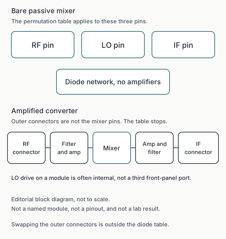
An amplified converter’s connectors already include filters, gain, and often the LO. Exchanging two of those connectors is a different job from exchanging pins on the diode network. The frequency converter guide treats the module as an assembly. This sheet does not tell you to run that module backwards.
An active mixer stops in the same place. So does an IQ mixer. Marki’s interchange sentence is limited to passive diode mixers. Mini-Circuits’ remark that a diode drawing’s structure shows up in other technologies does not carry drive limits or damage limits across that line. The datasheet of the part you are soldering is the limit.
Common mistake: Treating Marki’s passive-diode sentence as a license for an amplified converter, or treating Analog Devices’ refusal to guarantee the HMC554 and HMC773 swap as a reason to skip the reversed measurement Marki recommends when spurs are the problem. One of those is a class of diode mixers. The other is two part numbers in a 2015 reply.
Takeaway: If the connector label was written for an amplifier or a filter, leave the permutation table and open the module datasheet.
What the 2015 reply adds
In September 2015 an engineer asked Analog Devices whether a passive double-balanced mixer could have its RF and LO ports exchanged. The board change, from the HMC141 to the HMC554 or the HMC773, would swap those pins. The 29 September reply says the swap is not recommended and that performance is not guaranteed. In the swapped use they were asked about, the signal on the physical LO port still had to be +13 dBm for the HMC554 and the HMC773 to operate optimally.
The 28 September reply on the same thread states the LO drive as +13 dBm for both parts, a typical input 1 dB compression point of +11 dBm for the HMC554 and +12 dBm for the HMC773, and it says to keep the RF level below that point for linear operation. The +13 dBm figure in the later reply stays on the physical LO pin. The compression figures are the linear limit that reply gives for the RF level. After the pin names move, those two levels still belong to the pins the reply named, not to the signal names printed on a swapped layout. This page is not a datasheet. The EngineerZone page, as archived on 11 October 2026, labels the HMC554 obsolete. If that part is still the one on the board, the current data sheet sets the drive and the damage limit. Custody and RF verification for a discontinued part are the subject of obsolete RF component sourcing.
The 29 September reply also gives the leakage method, and it does not publish new isolation numbers. LO driven into the RF port: estimate LO leakage at the IF from the RF-to-IF isolation. RF signal driven into the LO port: estimate RF leakage at the IF from the LO-to-IF isolation. Both datasheet figures were taken with +13 dBm at the LO port. A different level at that port can change them. Isolation numbers a customer typed into the question are not repeated here, because the reply did not confirm them.
Marki’s FAQ points a different direction on LO power, and only for the passive diode class: exchanging the LO and RF ports can allow less LO power, with more conversion loss. Use that as a reason to measure. Leave the drive cell blank until the datasheet, or the 2015 reply for those two parts, fills it. When the problem is spurs, Marki says to flip the mixer and measure. Configuration A and Configuration B are Marki’s names for the two orientations of their own MMIC mixers.
Takeaway: Keep +13 dBm, +11 dBm, and +12 dBm attached to the HMC554 and HMC773 reply from September 2015, and let the current data sheet overrule them.
Save the sheet
Copy the topology row you used and the six before-and-after rows into the design note. Add the part number, the datasheet revision, and the LO level you will actually apply to the physical pin. Then read the frequency converter guide when the hardware in front of you is a module rather than a bare mixer.
Frequently asked questions
Can the IF and LO pins of a passive double-balanced diode mixer be exchanged?
Marki Microwave says any port of a passive diode mixer can be the LO, and that using the IF port as the LO puts significant harmonic content on the RF and LO ports. Confirm the IF pin's bandwidth, DC path, and drive on the datasheet. Analog Devices' 2015 reply about the HMC554 and HMC773 refuses to guarantee an RF and LO exchange on those parts. That reply is not an IF-pin rule for every mixer.
Which isolation figure applies after the RF and LO pins are exchanged?
For the HMC554 and the HMC773, Analog Devices said to estimate LO leakage at the IF from the RF-to-IF isolation when the LO enters the RF port, and RF leakage at the IF from the LO-to-IF isolation when the RF signal enters the LO port. Those figures were taken at +13 dBm on the LO port. A different level at that port can change them. Any other part needs its own datasheet table.
Does the passive diode swap table apply to an amplified converter?
No. The table is for a bare passive diode mixer. Converter connectors sit outside amplifiers and filters. An active mixer or an IQ mixer is outside Marki's passive-diode sentence. Drive and damage limits come from that part's datasheet.
Sources
- Are the LO and RF ports of a mixer physically interchangeable? — Marki Microwave Accessed October 12, 2026.
- Passive double balanced mixer RF/LO port swap (EngineerZone, 24-29 Sep 2015) — Analog Devices EngineerZone Accessed October 12, 2026.
- A Quick Guide to Mixer Topologies (7 March 2022) — Mini-Circuits Accessed October 12, 2026.