Direct answer
A downconverter translates a microwave RF to a lower IF so the rest of the receiver can filter and digitise it. An upconverter translates a lower IF or baseband up to a microwave RF for transmission or for a higher drive stage. They are not two grades of the same assembly and they are not interchangeable. High-side versus low-side LO is a separate decision: it chooses where the unused mixing product lands, 2 × IF from the wanted sideband in the real-mixer examples with LO > IF. RF filtering or IQ cancellation must control that product before the next stage. Zero-IF and more complex chains need a separate analysis.
Key takeaways
- Direction is the first decision: RF in / IF out, or IF in / RF out.
- The mixing identity is the same; only which port is the input changes.
- For the conventional real-mixer examples with LO > IF, the wanted and unused RF sidebands are separated by 2 × IF.
- Conversion loss, LO drive and isolation are mixer specifications, not “up” or “down” specifications.
- A converter with an embedded LO must be judged as an assembly, including that LO’s phase noise.
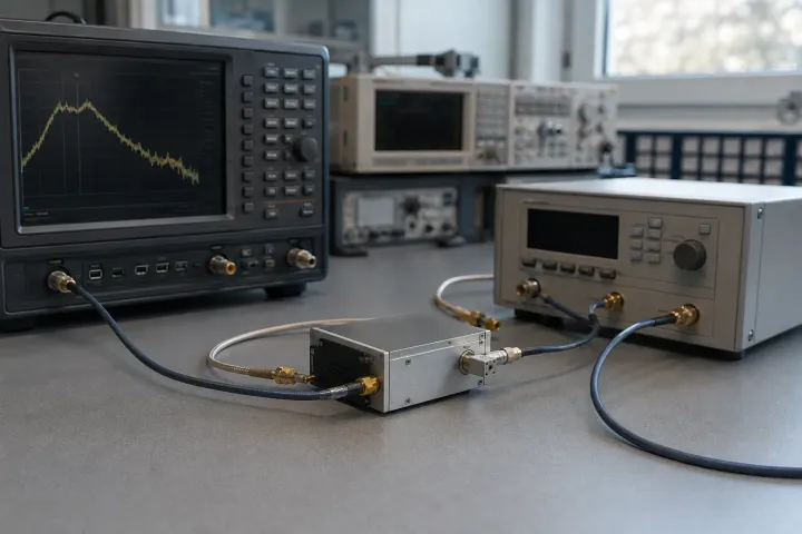
An upconverter and a downconverter are the same mixing identity read in opposite directions. That is the whole distinction, and it is enough to decide which assembly you are buying. What people then argue about — high-side or low-side, image rejection, conversion loss — is the RF / IF / LO plan, not a property of “up” versus “down”. This page sits in the signal chain section because the converter is a plan in a box.
Side by side
| Criterion | Downconverter | Upconverter |
|---|---|---|
| Signal in | RF from the antenna or previous RF stage | IF or baseband from the modulator or previous IF |
| Signal out | IF | RF |
| Mixing identity | |RF − LO| = IF | IF + LO = RF, or |LO − IF| = RF |
| Unwanted product | Image at RF, 2 × IF from the wanted RF | Unused sideband at RF, 2 × IF from the wanted RF |
| Where you filter it | RF preselector before mixing, or specified IQ cancellation | RF filter after mixing, or specified IQ sideband cancellation |
| Typical place in the chain | Receiver front end; analyser converter | Transmit chain; block upconverter; test source |
| LO’s job | Select which RF becomes this IF | Place the IF at the wanted RF |
| What “gain” usually means | Conversion loss, sometimes followed by IF gain | Conversion loss, sometimes followed by RF gain |
The conclusion
Buy a downconverter when the signal arrives at RF and the next stage cannot process that RF. The output is an IF. The mixer identity is |RF − LO| = IF. The image is a second RF, 2 × IF away in this plan; use RF preselection or the specified IQ image-reject architecture.
Buy an upconverter when the signal already exists at IF or baseband and must leave at RF. The output is an RF. The identity is IF + LO = RF (or |LO − IF| on the other sideband). The unused sideband is the twin of the image, and it must be rejected before the antenna or the next mixer.
Do not buy one and wire it backwards. A mixer die is often bilateral. A converter module is a set of filters, matches, LO routing and spurious traps built for one direction. Reversing the ports keeps the die and discards the plan.
High-side versus low-side is a packaging of the same 2 × IF geometry. It is not a third kind of converter.
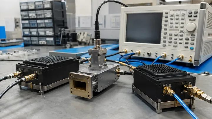
Conversion loss, LO-to-RF isolation, LO-to-IF isolation, input P1dB and IIP3 are mixer numbers. They show up on both assemblies. A module that hides the mixer behind an embedded LO adds that LO’s phase noise and harmonics to the specification; you are then buying an assembly, the same way a YTO-plus-driver is an assembly.
The unused product is the same shape
On a downconverter the unused input is called the image. On an upconverter the unused output is called the other sideband. In the conventional real-mixer examples below, LO > IF and the RF products lie on opposite sides of LO, separated by 2 × IF. Zero-IF, quadrature suppression and complex conversion chains need separate treatment.
Example, assumed inputs for downconversion: 10 GHz RF, 1 GHz IF, high-side LO:
- LO = 11 GHz
- Wanted IF = 1 GHz
- Image at 12 GHz also yields 1 GHz
Example, assumed inputs for upconversion: 1 GHz IF, 11 GHz LO (LO > IF):
- Wanted RF = 12 GHz (sum) or 10 GHz (difference)
- The product you did not choose is the unused sideband, 2 GHz away
The hardware response is a filter on the RF side. In receive, that is a preselector — YIG if the RF walks, cavity if it does not. In transmit, that is a bandpass on the wanted RF, often a cavity because the band is known and power is about to rise. YIG versus cavity is that choice.
What actually differs in the box
Direction changes three practical things.
Filter order. A downconverter filters RF, then mixes, then filters IF. An upconverter filters IF, then mixes, then filters RF. Swap those and the image or the unused sideband has already been translated into the band you meant to keep.
LO leakage. On a downconverter, LO–RF isolation decides how much of the LO escapes toward the antenna. On an upconverter, LO–RF isolation decides how much of the LO sits next to the wanted RF, IF away, and has to be filtered before a power amplifier. The isolation number is the same kind of number; the place it hurts is not.
Drive and limiting. A receiver downconverter is usually protecting a mixer from the antenna. A transmit upconverter is usually delivering a tone a later amplifier can use. Micro Lambda’s public bandpass-filter explanation, section 1 gives 0 to +10 dBm as an example of limited RF transfer through some YIG resonators. It is not a universal filter rating or damage threshold. For YIG filters, verify the model’s linearity and absolute maximum limits at its installed input plane, including any amplifier gain before it.
Embedded LO versus external LO
A converter brick with a built-in oscillator is convenient and opaque. The phase-noise plot, the lock time and the spurious lines are then properties of that oscillator, not of mixing as such. If the embedded source is a VCO, you have bought the VCO side of the source comparison. If you supply the LO, you can put a YTO or a DRO on that port and the converter becomes a mixer-plus-filters again.
For a wideband receiver the usual split is an external YIG-tuned oscillator into a downconverter, with a tracking preselector on the RF. For a fixed SATCOM block upconverter the usual split is an embedded DRO or a locked VCO and a cavity on the RF. The converter type did not force those choices; the frequency plan did.
A radar front end is this page plus a waveform: the receive path is a downconverter, the exciter path is often an upconverter, and both share an LO purity problem. That assembly is radar RF components.
Record the installed conversion path
Use a record for each direction; label products before placing filters. Evaluate a frequency converter module at the installed reference planes, including its LO and gain blocks.
| Field | Planned value / location | Measured or documented evidence |
|---|---|---|
| Input and wanted output | Fill: RF/IF bands, direction and selected product | Fill: gain and usable passband |
| Unselected product / LO leakage | Fill: frequencies, levels and suppression target | Fill: rejection and spur results |
| Filter / cancellation location | Fill: RF preselector, output filter or complete IQ path | Fill: installed ordering and rejection |
| Level and power limits | Fill: drive and gain before each block | Fill: linearity, limiting and damage conditions separately |
| Reference planes / LO state | Fill: connectors, cables, reference and amplifier state | Fill: conditions recorded with every result |
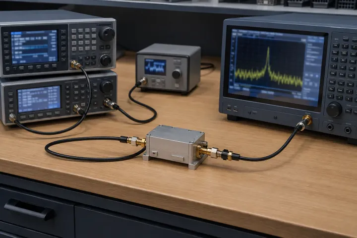
For upconversion, inject the documented IF and sweep the intended LO plan while observing wanted RF, other sideband and leakage. For downconversion, inject desired and image RF inputs and inspect the actual IF passband. Use the RF, IF and LO explainer to review the frequency arithmetic.
Takeaway: Compare conversion behavior at named input and output planes, with filters and amplifiers in their intended state.
Frequently asked questions
Can I use a downconverter backwards as an upconverter?
Sometimes the mixer die will mix in either direction. The filters, the LO plan, the matching and the spurious budget will not. A converter assembly is a frequency plan in hardware; reversing the ports does not reverse the plan.
What is high-side versus low-side on an upconverter?
For the real-mixer examples here, assume LO > IF. High-side means LO is above the wanted RF = LO − IF; the unused sum product is above LO. Low-side means LO is below the wanted RF = LO + IF; the unused difference product is below LO. Zero IF, IQ cancellation and multiple-conversion chains require their own sideband and filtering analysis.
Why do converters quote conversion loss instead of gain?
A passive mixer is a lossy translator. Conversion loss is the RF-to-IF (or IF-to-RF) power ratio at the wanted product, in dB. A module can show net gain from surrounding amplifiers, and an active mixer can itself provide gain. Read the architecture, noise figure and measurement conditions rather than assuming a passive mixing loss in every converter.
Does the converter set the image rejection?
Only if it includes the RF filter or uses an image-reject mixer topology. A bare mixer accepts both sidebands. The rejection number on a converter module is a property of the filters around the mixer, or of the I/Q cancellation, not of the word “up” or “down”.
Sources
- RF Mixer Theory — Downconversion, Image Frequency and Conversion Loss — RFLab Accessed August 28, 2026.
- The Role of the Preselector Filter in a Receiver Front End — RF Essentials Accessed August 28, 2026.
- Phase Noise Measurements with a Real-Time Spectrum Analyzer, chapter 7 — Berkeley Nucleonics Accessed August 28, 2026.
- MT-080: Mixers and Modulators, page 1 and Active Mixers — Analog Devices Accessed October 8, 2026.
- Bandpass versus band-reject YIG filters, section 1: limiting example — Micro Lambda Wireless Accessed October 8, 2026.
- I&Q Mixers: Image Reject and Single Sideband Conversion, figures 4–7 — Mini-Circuits Accessed October 8, 2026.