Direct answer
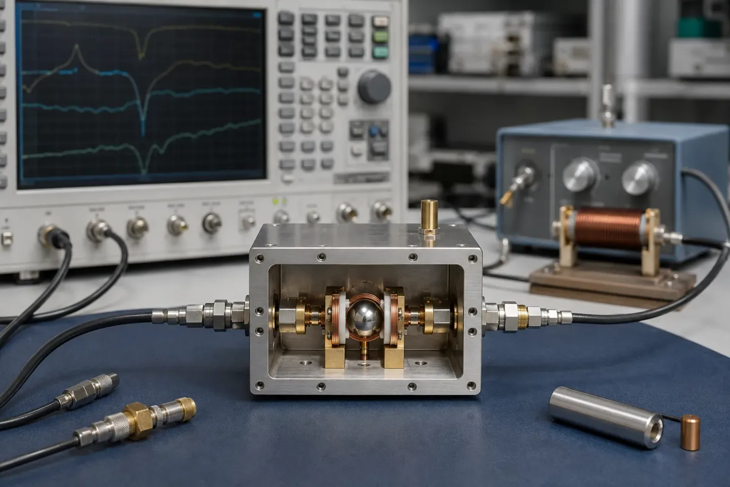
A YIG-tuned oscillator is a magnetically tuned microwave source: a negative-resistance active device locked to a YIG sphere whose resonant frequency follows an applied DC magnetic field. That mechanism buys octave-plus tuning with high spectral purity and unusually linear tuning, with a current driver, thermal control and calibration that belong in the specification. Choose a candidate when its model range, phase-noise plots and measured assembly recovery meet the required carrier, step size and error tolerance. Include PLL lock time if the delivered source is locked.
Key takeaways
- Specify the oscillator and its driver together; the driver sets tuning accuracy and speed.
- In the electromagnetic architecture discussed here, the main coil covers the wide span and the FM coil supplies limited correction for phase locking.
- Judge phase noise at the offsets your system integrates over, not at the datasheet's.
- Settling and drift include the magnet, driver, crystal temperature control and assembly; test the delivered system.
- Compare VCO and DRO candidates under the same carrier, offsets, bias, output level and lock conditions.
Selecting a YIG source from range alone can leave the driver or lock timing outside the system budget. Specify model coverage, noise conditions and assembly recovery together. This microwave component guide covers the inputs and evidence needed for that selection.
Key specifications
| Parameter | What it means | What it constrains |
|---|---|---|
| Tuning range | Frequency span reachable with the main coil | Whether one source covers your band, or you need several |
| Output power | Level at the connector, typically flat-ish across band | Mixer drive level and whether you need a buffer amplifier |
| Phase noise | L(f) at a stated offset and carrier | Receiver reciprocal mixing and achievable noise figure |
| Tuning linearity | Deviation of frequency from a straight line versus coil current | How much calibration and correction the system must carry |
| Hysteresis | Frequency difference approaching a point from above versus below | Absolute frequency accuracy without recalibration |
| Settling / lock time | Time to reach and stay within the allowed error after a stated step; include the loop if locked | Usable sweep or hop deadline for the delivered assembly |
| Operating temperature | Range over which specifications hold | Thermal design and the correction table you need |
Parameter meanings are general to the device class. For values, work from the specific part's datasheet — ranges vary widely across models and grades.
Where it sits in the chain
A YTO is a frequency source, one of the families collected under microwave and RF components. In a receiver it is usually the first local oscillator, feeding a mixer or converter; in test equipment it is the sweeper. Its two defining characteristics — very wide tuning and low phase noise — are exactly what a broadband receiver front end needs, because the LO has to reach every frequency the receiver covers without polluting the conversion.
How it works, briefly
The full mechanism is covered in how YIG oscillators work and the material physics in what YIG is. In short:
- The YIG sphere is the frequency-determining resonator, with high unloaded Q from its narrow ferrimagnetic resonance linewidth.
- The active device supplies gain and negative resistance across the band; it does not set frequency.
- For the electromagnetic architecture here, the main coil provides broad tuning; its driver and frequency step affect recovery.
- The FM coil provides limited correction for phase locking; verify its usable span and response with the loop.
Micro Lambda’s YTO definition, page 1, describes thermal control of the YIG sphere. Frequency stability is therefore not solely a magnetic-circuit property: crystal temperature control, mounting and the complete driver/assembly contribute. Include warm-up and enclosure conditions in the acceptance record.
For representative model coverage, the manufacturer’s public electromagnetic oscillator table lists MLOB-0208: 2–8 GHz and MLOS-1840: 18–40 GHz in its model and frequency columns. These are separate published model ranges, not one device’s span or a recommendation. Use the selected model’s dated datasheet for power, noise, environmental grade and guaranteed limits.
The two coils, and why the split matters when you specify
The main-coil and FM-coil roles describe the electromagnetic architecture in Micro Lambda’s YTO note, pages 3–4. Confirm which port was used, the excursion, driver, temperature and error band for every response claim. A small correction and a broad step are different tests; neither proves the other’s assembly lock time.
For a sweeping source, test the required tuning steps. For a locked source, include main-coil acquisition, available FM correction and loop recovery as applicable. Accept the source only after the specified frequency error and lock criteria hold.
Reading the phase noise number honestly
The headline dBc/Hz figure is the most-quoted and least-useful number on a YTO datasheet, because it is quoted at whichever offset flatters the part.
What matters is the offset your system integrates over. A receiver rejecting a strong adjacent signal cares about the mid-range offsets where reciprocal mixing happens. A coherent processor cares close-in. A wideband downconverter cares about the far-out floor because that sets its noise figure. Understanding phase noise covers how to read the plot rather than the headline.
One consequence specific to YTOs: because they are fundamental oscillators rather than multiplied sources, they avoid the 20·log₁₀(N) penalty a multiplier chain pays. A YTO that looks unremarkable against a multiplied source’s headline number can still be the quieter option at frequency.
Against the alternatives
| Criterion | YIG-tuned oscillator | Varactor-tuned VCO | Dielectric resonator oscillator |
|---|---|---|---|
| Tuning range | Octave or more | Wide, but typically less | Essentially fixed |
| Tuning linearity | Very linear in current | Non-linear in voltage | Not applicable |
| Phase noise | Compare required carrier/offset plots | Use matching bias, output and lock conditions | Use the same conditions; no class-wide winner |
| Settling time | Measure step, driver and allowed error; include lock | Separate device response from PLL recovery | Measure lock/trim recovery if used |
| Power consumption | Continuous coil current | Low | Low |
| Size | Large; magnet dominates | Small, often a single package | Small |
| Magnetic sensitivity | Significant | Negligible | Negligible |
| Typical use | Wideband LO, sweepers | Agile synthesis, PLL blocks | Fixed low-noise reference |
The pattern is consistent: YIG buys range and purity, and pays in speed, power and size. For a fixed frequency plan, compare a DRO under the same phase-noise conditions. For rapid frequency hopping, verify the complete YIG assembly’s settling specification against the required step and error tolerance. The full decision, including a decidable conclusion, is YIG oscillator vs VCO vs DRO.
Selection criteria
That last question is not an afterthought on a component with a long design life. See obsolete RF component sourcing for how to handle it.
Advantages and limitations
Broad continuous tuning and fundamental operation can make an electromagnetic YTO useful as a receiver or instrument LO. The trade-off is integration: current drive, thermal control, magnetic clearance and calibration. Its suitability for a radar or agile receiver follows the waveform’s measured step-and-lock budget, not the application name; see radar RF components.
Buying and lifecycle
YTOs are low-volume, long-life parts, and that shapes procurement more than the specification does.
- Specify the assembly, not the resonator. Oscillator plus driver plus calibration is the unit that has a performance figure. Buying the pieces separately transfers the integration to you, along with the responsibility for the phase noise number.
- Ask what the datasheet figure was measured with. A phase noise plot is taken with a particular driver, at a particular carrier, at a particular temperature. Any of those changing changes the number.
- Check production status early. Programme lifetimes in this field routinely outrun component lifetimes, and a magnetically tuned source is not a drop-in replacement for another vendor’s magnetically tuned source. The calibration is part specific.
- Plan for the calibration data. Whatever corrects linearity and drift has to be stored, versioned and reproducible on a repaired unit. That is a systems problem, not a component one.
The general version of this discipline — traceability, date codes, incoming inspection, obsolescence — is in sourcing and quality.
Testing and integration notes
- Measure phase noise on the locked assembly you will ship, not the bare oscillator, if it runs in a loop.
- Characterise hysteresis by approaching test frequencies from both directions; the difference is the number your calibration has to absorb.
- Verify settling against your actual step size. A settling figure for a full-band step tells you little about a small correction, and vice versa.
- Check frequency accuracy across the enclosure temperature range, not at ambient.
- Confirm magnetic clearance in the mechanical layout before the enclosure is fixed, not after.
Turn requirements into an acceptance record
Micro Lambda’s YTO definitions group requirements into RF, magnet, power and environmental specifications. Its permanent-magnet application paper discusses construction, magnetic gap adjustment and ruggedization. Use those public documents to define the delivered assembly and request evidence; they do not establish a universal cost or performance result.
| Requirement to fill in | Operating / test conditions | Supplier evidence to record | Acceptance result to fill in |
|---|---|---|---|
| Frequency range and architecture: ___ | Start/stop: ___; electromagnetic or permanent magnet: ___; control current: ___ | Model datasheet and tuning-port limits: ___ | Coverage / port check: ___ |
| Frequency step and ready deadline: ___ | Step size/direction: ; error band: ±; driver/reference/loop: ___; temperature: ___ | Settling definition and measured transition record: ___ | Time into and staying in tolerance; lock state: ___ |
| Phase noise and output: ___ | Carrier: ___; offsets: ___; locked/free-running: ___; bias/load/output level: ___ | Comparable plot and guaranteed/typical classification: ___ | Noise/output at required points: ___ |
| Repeatability and thermal drift: ___ | Approach direction: ___; enclosure temperature: ___; warm-up/heater state: ___ | Calibration, hysteresis and thermal test record: ___ | Frequency error by condition: ___ |
| Package and delivered integration: ___ | Mounting/RF/supply/control interfaces: ___; bare or driver-equipped: ___ | Drawing, driver revision, calibration and test documents: ___ | Interface and configuration check: ___ |
Retain plots, calibration and conditions with the serial number. For a locked source, include reference-interruption recovery and correction authority in the agreed test plan. Revisit YIG versus VCO versus DRO if the required coverage, timing or power cannot be demonstrated; use obsolete RF component sourcing for traceability and incoming evidence.
Specification priorities by application
Micro Lambda’s markets overview identifies test equipment, electronic-intelligence receivers, radar and monitoring uses. The priorities below are an engineering reading of those roles, checked against its YTO definitions and Keysight’s Spectrum Analysis Basics; they are questions for a system specification, not measured performance claims.
| Application | Start the comparison with | Condition that must accompany the answer |
|---|---|---|
| EW or wideband intercept receiver LO | Coverage, phase noise near strong signals and tuning recovery | Actual frequency step, required settling tolerance and relevant carrier offsets |
| Test instrument or swept source | Repeatable tuning, spectral purity and stable output | Sweep direction, dwell time, temperature and calibration state |
| Radar LO or exciter | Noise at coherent-processing offsets and repeatable frequency changes | Locked-loop configuration, reference and timing definition; use the radar guide for system requirements |
| Spectrum-monitoring receiver | LO coverage and coordination with the preselector | Both devices’ settled state and passband alignment before a reading is accepted |
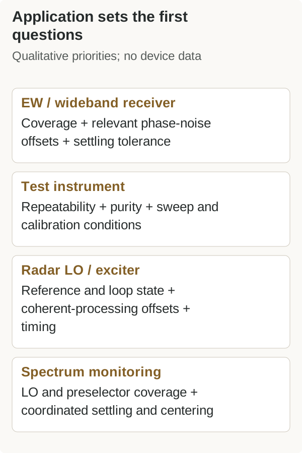
There is no single winning specification for an entire application label. Write the operating condition beside the requirement, then check the delivered oscillator, driver and loop together.
Related guides
- What is YIG — the material and the tuning mechanism
- How YIG oscillators work — the loop, the coils and the driver
- YIG oscillator vs VCO vs DRO — when the alternatives win
- Understanding phase noise — how to read the parameter that usually decides the choice
- YIG-tuned filters — the usual tracking preselector
- Radar RF components — how the same source is constrained by a waveform
Frequently asked questions
Do I need the driver from the same vendor?
Not necessarily, but the oscillator and driver form one control system. Buying them separately means you own the integration — coil current accuracy, thermal compensation and calibration all become yours.
How fast can a YIG oscillator change frequency?
Use measured recovery for the actual frequency step, coil, driver, temperature and allowed error. Micro Lambda’s YTO note defines settling as entering and staying within an error band (page 4, Figure 7). Include PLL reacquisition for a locked assembly; a fast FM correction does not demonstrate full-span hop performance.
Is the tuning repeatable?
It is highly linear but not perfectly repeatable. Magnetic hysteresis means the frequency reached depends slightly on the direction of approach, so systems needing absolute accuracy calibrate and correct, or always approach from the same side.
Can I use one near a magnet or a motor?
With care. The tuning field is the control variable, so external magnetic fields are an error source. Shielding and physical separation are normal parts of the mechanical design.
Sources
- Electromagnetic YIG Oscillators — table rows MLOB-0208 and MLOS-1840 — Micro Lambda Wireless Accessed October 8, 2026.
- YIG Tuned Oscillators — thermal control (p. 1), magnet specifications (p. 3), settling (p. 4, Fig. 7) — Micro Lambda Wireless Accessed October 8, 2026.
- Permanent Magnet YIG Tuned Oscillators — construction and ruggedization discussion — Micro Lambda Wireless Accessed October 8, 2026.
- Markets — test equipment, receivers, radar and monitoring applications — Micro Lambda Wireless Accessed October 8, 2026.
- Spectrum Analysis Basics — phase noise and microwave preselection — Keysight Technologies Accessed October 8, 2026.
- MT-086 — Fundamentals of Phase Locked Loops (PLLs) — Analog Devices Accessed October 8, 2026.