Direct answer
Compare YIG oscillator phase noise at the same carrier and offset points. Record the heater state, tuning driver and analyzer settings alongside each trace. Start with the conditions checklist below, then use the heater and driver sections to review the setup.
Key takeaways
- Record carrier frequency and offset points with each phase-noise result.
- Keep heater startup, steady-state current and warm-up criteria together.
- Include the tuning driver and analyzer configuration in the comparison record.
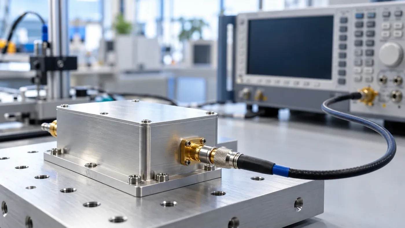
Before comparing YIG oscillator phase noise, put the test conditions beside the trace. Start with the carrier and close-in offset points, then work through heater warm-up, coil driver setup and analyzer configuration. Use the checklist at the end to prepare a comparison record.
Explore the YIG technology hub for the wider topic, or go straight to how YIG oscillators work for the tuning mechanism.
Read the offset before comparing the result
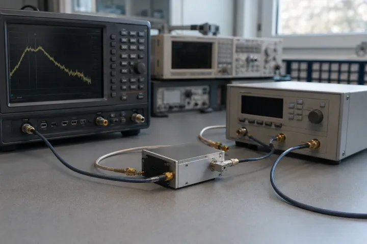
Phase noise amplitude is expressed in dBc/Hz, relative to carrier power and normalized to a 1 Hz bandwidth. The horizontal axis is the single-sideband frequency offset from the carrier.
In the Keysight SSA-X phase-noise setup, the measurement range is determined by start and stop offsets relative to the carrier. In that SSA-X setup, the resolution bandwidth ratio specifies bandwidth as a percentage of each half-decade offset interval. For a close-in comparison, explicitly record the start offset and every offset point of interest. Keep the carrier frequency beside those entries.
A model-specific specification example
MLVG-0618 maximum phase noise at 10kHz offset is -100 dBc/Hz. MLVG-0618 maximum phase noise at 100kHz offset is -125 dBc/Hz. The Micro Lambda MLVG guaranteed specifications apply at 0º to +65º C case temperature.
Keep each offset attached to its corresponding limit, and label a measured result separately from a maximum specification. For a candidate comparison, request the carrier test point and temperature condition along with the trace. Use the phase-noise guide for broader plot terminology.
Heater warm-up and PTC stabilization
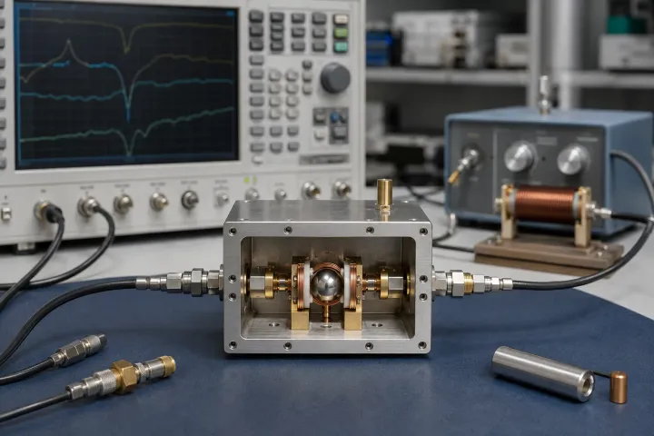
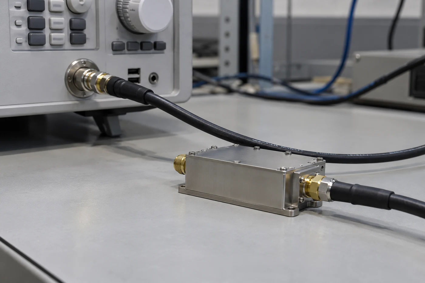
For its heater-equipped YIG devices, Micro Lambda describes a heater that raises resonator temperature to approximately +80-85 degrees C. The material at the elevated temperature is less susceptible to emitting spurious tones. The heater also affects temperature compensation over extended temperature ranges.
Use the heater terminology precisely. In Micro Lambda’s oscillator specification definitions, the following distinctions apply:
- Heater surge current is the peak current drawn on initial power-up.
- Steady-state heater current is the current required during normal operation after reaching steady state.
- Warm-up time is the minimum time needed for the unit to meet all specifications.
For a YIG heater warmup stability check, record the elapsed warm-up, heater supply, startup current, steady-state current and case condition. Apply the warm-up criterion for the device being evaluated.
What the PTC heater description establishes
In the prior-art heater assembly described in the YIG sphere heater patent, positive temperature coefficient barium titanate heater pellets transfer heat to the heater block. At room temperature the barium titanate has low resistance, so high current causes rapid heating. As the pellet cools, resistance drops, current increases, and temperature rises. The temperature of the barium titanate chip remains relatively constant.
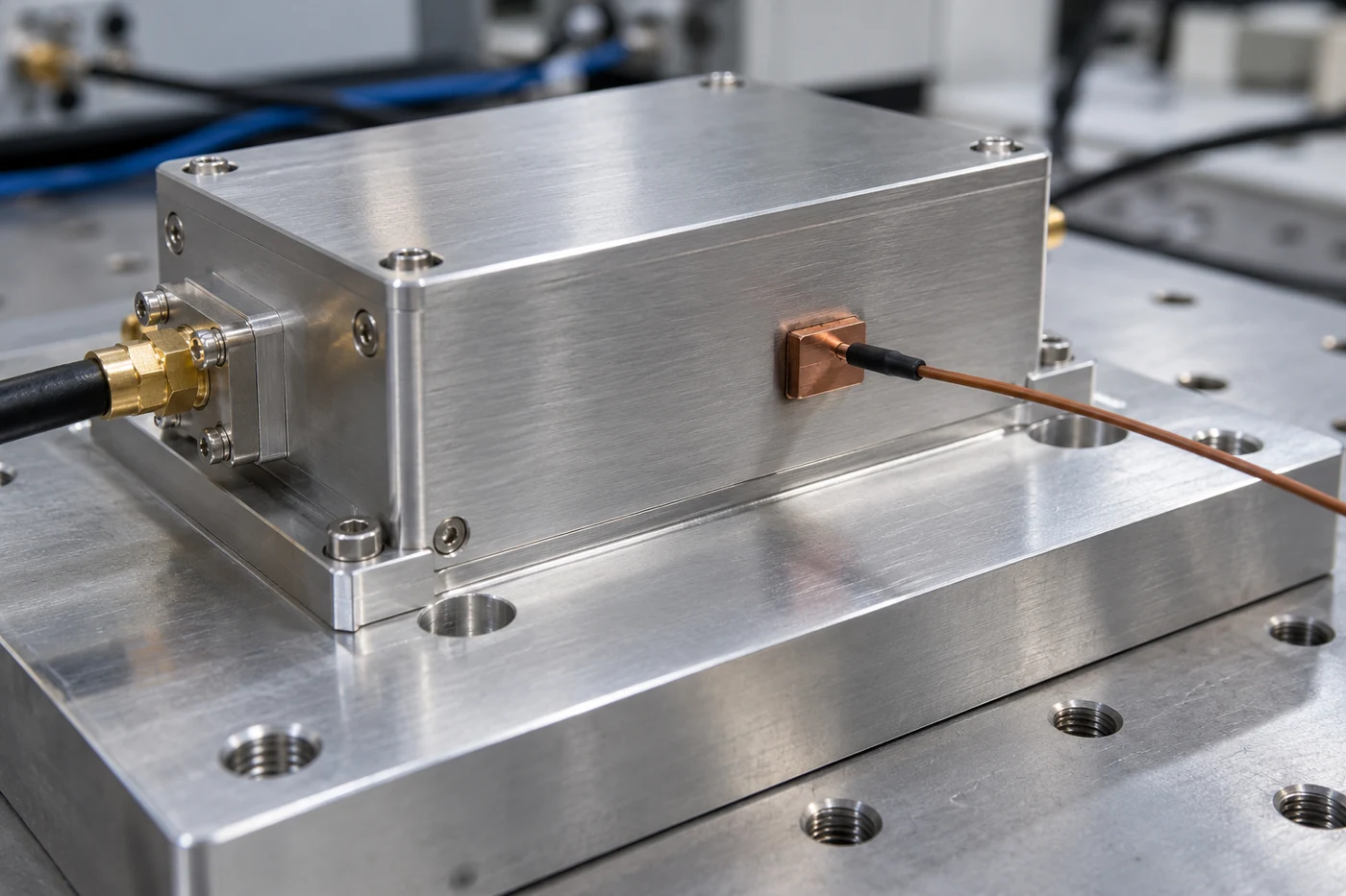
Keep the heater-chip observation and the complete oscillator’s warm-up criterion as separate entries in the test record. Capture the mounting arrangement alongside the heater observations.
YIG coil driver current noise: examine the tuning path
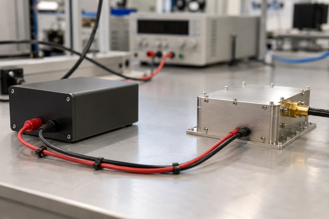
YIG drivers convert control commands to tuning current. For Micro Lambda YIG devices, a constant current source between the supply and the YIG device is required because tuning-coil resistance and impedance change.
In the ideal YIG resonant case, magnetic field and frequency are linearly related to magnetising current. In the historical circuits discussed in Designing YIG Drivers, connecting the tuning coil at the emitter can reduce ripple-induced FM, with a trade-off in speed.
Start the driver review with the actual driver identity, tuning current, coil connections and filtering. Request current-noise information for that configuration. Keep the main tuning path and any separate modulation connection explicit in the record.
For a model-specific sensitivity entry, MLVG-0618 typical main-coil sensitivity is 18 MHz/mA. Preserve the typical qualifier when recording this value, and use the candidate’s own sensitivity for its tuning-path review.
For broader device selection, continue to the YIG oscillator component guide.
Check the analyzer and the bench
Thermal noise can limit the phase-noise measurement floor for weak signals. Too much input attenuation can lower signal power until thermal noise degrades the noise floor. Too little attenuation can overload the circuit and produce bad measurement results. Record input level and attenuation together.
Cross-correlation improves the measurement noise floor. Noise from the signal under test is coherent and is not reduced by cross-correlation. Averaging smooths the trace but takes significantly more time. Save the correlation and averaging settings with the result.
Spurs are better expressed in dBc. Random and deterministic phase-noise components need separate treatment in system-performance calculations. Keep discrete-spur observations separate from the random-noise entries.
Mechanical vibration can modulate the magnetic field and frequency of a YIG resonator. Include a bench-disturbance note when capturing the trace.
YIG phase noise test conditions checklist
Use these prompts when preparing a test or requesting a comparable trace. Copy the fields into the measurement record and attach the applicable device specification.
Device and frequency
- Identify the oscillator model and configuration.
- Enter the carrier frequency, start and stop offsets, and individual comparison offsets.
- Label each result as a measured value, typical value or maximum specification.
- Record free-running or locked operation; include reference and loop settings when applicable.
Heater and mounting
- Enter the heater supply and elapsed warm-up.
- Record startup and steady-state heater current separately.
- Attach the device’s warm-up criterion.
- Describe case condition, ambient condition and mounting arrangement.
Tuning driver
- Identify the current driver and actual tuning current.
- Record main-coil sensitivity with its original qualifier.
- Describe coil filtering, shunt components and the modulation-port connection.
- Attach available driver current-noise information for the configuration under test.
Analyzer and result
- Identify the analyzer and measurement mode.
- Record input level, attenuation, offset range and resolution-bandwidth settings.
- Record averaging and cross-correlation settings.
- List discrete spurs separately and note mechanical disturbances.
- Attach the trace and review the completed conditions record before drawing a comparison.
For the next selection step, use the YIG oscillator, VCO and DRO comparison.
Sources
- Keysight — Infiniium Phase Noise Analysis
- Keysight — Configuring Phase Noise, SSA-X
- Micro Lambda Wireless — MLVG Series Data Sheet
- Micro Lambda Wireless — Support FAQ
- Micro Lambda Wireless — Technology Description: YIG Tuned Oscillators
- Trump — Low profile heater and support assembly for YIG spheres
- Micro Lambda Wireless — Application Note: YIG Drivers / FM Coil Drivers
- Nagarajan and Prema — Designing YIG Drivers
- SiTime — Phase Noise Measurement Guide for Oscillators
- Tektronix — Capturing and Measuring Microphonics and Phase-Hits with the RTSA