Direct answer
A quarter wave transformer is a transmission-line section one quarter wavelength long placed in series between a feedline of characteristic impedance Z0 and a purely resistive load RL. Setting its characteristic impedance Z1 to the geometric mean sqrt(Z0 times RL) cancels input reflections at the design frequency so all incident power reaches the load.
Key takeaways
- Set the quarter-wave section characteristic impedance Z1 to the geometric mean of the feedline Z0 and purely resistive load RL.
- Calculate physical length from guided wavelength using wave propagation velocity vp or microstrip effective dielectric constant rather than free-space wavelength.
- Rotate any complex load along a constant-VSWR circle on the Smith chart to a purely real resistance Rin before inserting a quarter-wave section.
- Use multisection maximally flat or Chebyshev cascades when required passband bandwidth or impedance ratio exceeds single-section limits.
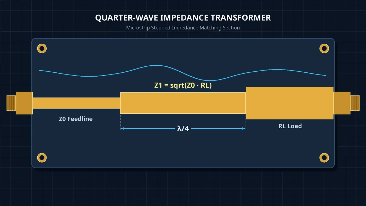
A quarter wave transformer is a transmission-line section one quarter wavelength long placed in series between a feedline of characteristic impedance Z0 and a purely resistive load RL. Setting its characteristic impedance Z1 equal to the geometric average sqrt(Z0 times RL) produces zero input reflection at the design frequency so all incident power reaches the load.
Explore the RF engineering hub for related design fundamentals, review RF voltage-to-power conversion across reference impedances when working between different characteristic impedance standards, or see how matching sections integrate into radar RF front-end components.
How does a quarter-wave transformer work?
A quarter-wave transformer sits in series with the load and acts as an impedance inverter whose characteristic impedance and one-quarter-wavelength electrical length cancel reflections at the input. Reflected waves from its input and load interfaces arrive out of phase at the design frequency, driving the input reflection coefficient Γin to zero on a lossless line.
Unlike a shunt stub that terminates in a short or open circuit and relies solely on length, the λ/4 series line matching section uses both its length and its characteristic impedance to produce the required impedance transformation. When a transmission line terminates in a mismatched load, reflected voltage adds to incident voltage while reflected current subtracts from incident current because the reflected wave travels in the opposite direction.
Standing-wave duality and impedance inversion
One quarter wavelength away from an open-circuit termination, the voltage and current oscillations match those at a short circuit, and vice versa. That dual standing-wave relationship means a λ/4 section inverts an open circuit into a short circuit and transforms a short circuit into an open circuit.
RF designers apply that short-to-open inversion directly in DC bias networks. Feeding DC bias through a λ/4 transformer turns the RF short circuit of the DC supply into an RF open circuit at the main signal line, isolating the RF path without loading the carrier.
Two-interface reflection cancellation
Viewed as a cascade of two two-port interfaces terminated in RL, the quarter-wave section creates one reflection at the feedline-to-transformer step and a second reflection at the transformer-to-load step. When the section impedance equals the geometric mean, the connector S11 reflection value equals the load reflection coefficient so the returning waves cancel at the input.
At upper VHF through microwave frequencies, one quarter wavelength is short enough to fit inside practical products while remaining large enough to manufacture within normal engineering tolerances.
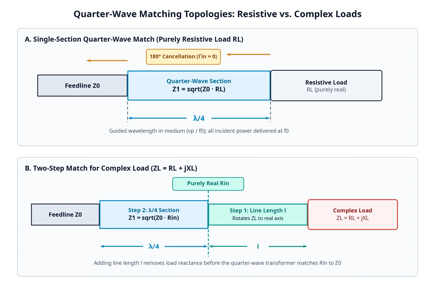
Takeaway: Place the quarter-wave section in series with a purely real resistance so both stepped interfaces generate equal, opposing reflections that cancel at the design frequency.
What is the quarter-wave transformer impedance formula?
To match a purely resistive load RL to a transmission line of characteristic impedance Z0, set the quarter-wave section characteristic impedance Z1 equal to the geometric average sqrt(Z0 times RL) and set its physical length to one quarter of the guided wavelength. At that design frequency, Γin equals 0 and all incident power reaches RL.
According to the University of Kansas quarter-wave transformer derivation, both the impedance condition and the physical length condition must hold together. Calculating Z1 accurately does not produce a match if the physical length misses one quarter of the guided wavelength in the transmission medium.
Guided wavelength and propagation velocity scaling
Guided wavelength along the matching section depends on the wave propagation velocity vp in the transmission medium rather than free-space light speed alone. Because wavelength scales inversely with frequency, physical quarter-wave length shrinks as operating frequency increases:
- In vacuum, one full wavelength at 1 GHz is 30 cm (0.3 m), making a transmission line length of 7.5 cm equal to one quarter wavelength.
- In vacuum, one full wavelength at 3 GHz is 10 cm (0.1 m), demonstrating how higher microwave frequencies reduce physical section length.
When building on a dielectric substrate instead of air or vacuum, the reduced propagation velocity vp shortens the guided wavelength further, so engineers must size the physical trace to the medium rather than free space.
Lumped-element T and Pi equivalents at lower frequencies
At lower frequencies where a distributed quarter-wave transmission line becomes impractically long, designers can emulate the same impedance-inversion properties with a lumped-element T or PI network. Each lumped element in the T or PI equivalent is sized to have a reactance equal to the target characteristic impedance Zo of the simulated quarter-wave section.
| Matching topology | Placement relative to load | Design parameters (units) | Best operating regime | Key limitation |
|---|---|---|---|---|
| Distributed λ/4 transformer | Series line section ahead of load | Characteristic impedance Z1 (ohms) and guided length λ/4 (cm or mm) | Upper VHF through microwave frequencies | Narrow bandwidth; requires purely real load resistance |
| Lumped T or PI equivalent | Series lumped network ahead of load | Element reactances equal to Zo (ohms) at design frequency | Lower RF frequencies where physical λ/4 is too long | Narrowband around design frequency; component parasitics |
| Shunt stub matcher | Shunt branch terminated in open or short | Stub length and placement distance (guided wavelengths) | Single-frequency complex load matching | Relies on stub termination rather than series impedance step |
Takeaway: Compute Z1 as the geometric mean of Z0 and RL, then convert λ/4 to physical length using the medium propagation velocity vp or switch to a lumped T or PI equivalent at low frequencies.
What limits quarter-wave transformer bandwidth?
A single-section quarter-wave transformer is inherently narrowband because its fixed physical length equals exactly one quarter wavelength at only one design frequency. As frequency shifts away from center, electrical length changes, input reflection rises, and usable bandwidth narrows rapidly as the load-to-line impedance ratio ZL/Zo increases or when load reactance is present.
As documented in UC Santa Barbara impedance matching notes, RF practice commonly defines an acceptable impedance match as SWR below 1.5. Holding a single quarter-wave section inside that SWR threshold becomes progressively harder under three physical constraints.
Off-center frequency phase error
The transmission-line section achieves Γin equal to 0 at one exact signal frequency. Moving above or below that center frequency alters the electrical length of the fixed physical section so it no longer spans one quarter wavelength, degrading impedance-inversion accuracy and raising input reflection.
Impedance ratio ZL/Zo sensitivity
Single-section bandwidth depends directly on the normalized load-to-line impedance ratio ZL/Zo. Matching bandwidth widens when RL (or transformed resistance Rin) sits close to Z0 and tightens sharply as the ratio grows; evaluating a maximum SWR of 1.5 at an impedance ratio of 4 illustrates how rapidly single-section passband width contracts under large steps.
Load reactance and the Bode-Fano ceiling
Practical RF loads typically carry substantial reactance alongside resistance rather than acting as pure resistors. Even when a matching network cancels reactance at center frequency, a general physical limit—the Bode-Fano ceiling—restricts the bandwidth over which an arbitrarily good match can be achieved across a reactive load. For related port-termination reflection behavior in mixer stages, see our mixer IF port termination and conversion-loss ripple guide.
Takeaway: Check both the normalized impedance ratio ZL/Zo and load reactance before committing to a single quarter-wave section against an SWR below 1.5 target.
How do you trace a quarter-wave match on a Smith chart?
To match a complex load on a Smith chart, first add a transmission-line length toward the generator to rotate the normalized load impedance along a constant-VSWR circle until it crosses the real resistance axis at a purely real value Rin. Then insert a quarter-wave section with characteristic impedance Z1 equal to sqrt(Z0 times Rin) to bring Rin to Z0.
Because a single quarter-wave section cannot cancel load reactance directly, adding an initial length of transmission line ahead of the load makes the impedance completely real before the impedance-stepping section begins.
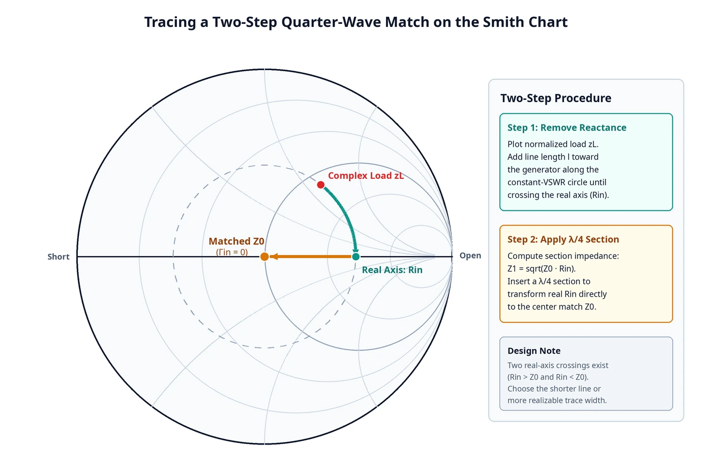
Step-by-step Smith chart workflow
Follow this two-step sequence whenever the measured or modeled load contains non-zero reactance:
| Step | Action on Smith chart | Impedance state | Required condition |
|---|---|---|---|
| 1. Plot load | Normalize complex load ZL to feedline Z0 | Off the real axis (non-zero reactance) | Valid single-frequency load measurement |
| 2. Rotate to real axis | Move clockwise toward generator along constant-VSWR circle by line length l | Purely real input resistance Rin | Stop at first real-axis crossing that yields a practical trace impedance |
| 3. Size quarter-wave section | Compute Z1 equal to sqrt(Z0 times Rin) | Stepped characteristic impedance Z1 (ohms) | Line impedance must remain manufacturable on chosen PCB stackup |
| 4. Apply λ/4 transform | Insert series λ/4 section at the Rin reference plane | Matched to Z0 (Γin equal to 0) | Physical length equals one quarter guided wavelength at design frequency |
Takeaway: Rotate a reactive load onto the real axis along a constant-VSWR circle first so the quarter-wave section sees a purely real resistance Rin.
How do you lay out a microstrip quarter-wave transformer?
Microstrip supports a quasi-TEM dominant mode whose electric fields split between the substrate and air, so physical quarter-wave length must use the effective dielectric constant rather than bulk permittivity or free-space wavelength. At microwave frequencies, use low-loss RF laminates instead of FR4 and route bends with a curve radius of at least 3 times the strip width.
As explained in the microstrip transmission-line reference, wave propagation velocity in a microstrip trace lies between the speed of radio waves in the substrate and the speed of radio waves in air. Treating the trace as an equivalent homogeneous medium with an effective dielectric constant yields the true propagation velocity and guided quarter-wavelength needed to hit the target center frequency.
Substrate dielectric loss and quasi-TEM dispersion
Because longitudinal field components remain small, the dominant microstrip mode behaves as quasi-TEM, with an effective dielectric constant that accounts for the air-dielectric field split. Standard FR4 substrates frequently suffer excessive dielectric loss at microwave frequencies, so high-frequency quarter-wave matching sections perform more reliably on dedicated low-loss RF laminates.
Low-reflection microstrip bend geometry
When board space requires folding or meandering a quarter-wave section, avoid sharp right-angle corners. An abrupt 90° bend in a microstrip reflects a significant portion of the signal back toward the source, transmitting only part of the wave around the corner. Curving the strip in an arc with a radius of at least 3 times the strip width maintains a low-reflection transition.
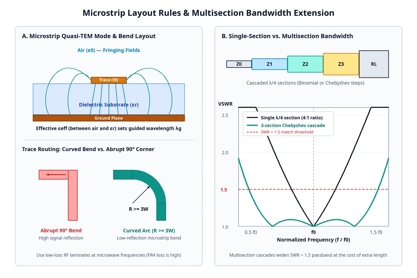
Takeaway: Size every microstrip quarter-wave trace using effective dielectric constant, avoid FR4 at microwave frequencies, and curve any bends to a radius of at least 3 times the strip width.
When do you use a multisection Chebyshev transformer instead?
Switch to a multisection Chebyshev or maximally flat transformer whenever the required operating bandwidth or load-to-line impedance ratio exceeds what a single quarter-wave section can hold below your SWR target, such as SWR below 1.5. Cascading multiple stepped λ/4 sections widens the passband substantially in exchange for greater physical board length.
Comparing single-section, maximally flat, and Chebyshev cascades
Overcoming the narrow bandwidth of a single quarter-wave section requires dividing the total impedance step across multiple cascaded λ/4 sections whose characteristic impedances follow either a maximally flat (binomial) or Chebyshev (Tchebyscheff) taper:
| Architecture | Passband reflection shape | Bandwidth capability | Physical footprint | When to select |
|---|---|---|---|---|
| Single-section λ/4 | Single zero-reflection null at center frequency | Narrow; degrades quickly as ZL/Zo rises | Compact (one guided λ/4) | Narrowband links with moderate resistive impedance ratios |
| Multisection maximally flat (binomial) | Smoothly flat response around center frequency | Broad around center, slower band-edge rolloff | Longer (multiple cascaded λ/4 sections) | Designs prioritizing minimal center-band reflection over maximum edge bandwidth |
| Multisection Chebyshev (Tchebyscheff) | Controlled equal-ripple reflection across passband | Widest passband for a given section count and SWR limit | Longer (multiple cascaded λ/4 sections) | Wideband microwave stages requiring maximum passband under an SWR limit such as 1.5 |
Engineering verification checklist before fabrication
Before releasing a quarter-wave matching layout for fabrication, verify each design boundary:
- Confirm whether the load is purely resistive or requires an initial phase-shifting line length l to reach a purely real impedance Rin.
- Verify that the physical λ/4 length uses the medium propagation velocity vp or microstrip effective dielectric constant rather than free-space wavelength.
- Check the normalized impedance ratio ZL/Zo against your target SWR limit, such as SWR below 1.5, to decide between a single section and a multisection maximally flat or Chebyshev cascade.
- Inspect PCB routing for microwave dielectric loss on FR4 and ensure any trace turns avoid abrupt 90° bends by using a radius of at least 3 times the strip width.
For system-level power accounting alongside matching-stage return loss, see our RF link budget calculation and fade margin guide.
Takeaway: Trade extra physical length for a multisection Chebyshev or maximally flat cascade whenever a single λ/4 section cannot hold target SWR across the full signal band.
Sources
Frequently asked questions
What is the impedance formula for a quarter-wave transformer?
To match a purely resistive load RL to a feedline with characteristic impedance Z0, set the quarter-wave section characteristic impedance Z1 to the geometric average sqrt(Z0 times RL) and its physical length to one quarter of the guided wavelength at the design frequency.
Can a single quarter-wave transformer match a complex reactive load directly?
No. A single quarter-wave section matches only a purely real resistance. For a complex load, first insert a phase-shifting length of transmission line ahead of the load to rotate its impedance to a purely real value Rin, then match Rin to Z0 with a quarter-wave section.
Why is a single-section quarter-wave transformer narrowband?
The fixed physical trace equals exactly one quarter wavelength at only a single design frequency. As signal frequency moves away, electrical length changes, impedance inversion degrades, and input reflection rises faster as the load-to-line ratio ZL/Zo increases.
How do you calculate the physical length of a microstrip quarter-wave transformer?
Because microstrip fields travel partly in the dielectric substrate and partly in air in a quasi-TEM mode, determine guided wavelength from the effective dielectric constant rather than bulk substrate permittivity or free-space wavelength.
When should you replace a single quarter-wave section with a Chebyshev transformer?
Switch to a multisection Chebyshev or maximally flat cascade whenever a single section cannot hold SWR below your match target, such as SWR below 1.5, across the required operating band or impedance ratio.
Sources
- Quarter-wave impedance transformer — Wikipedia
- The Quarter Wave Transformer — University of Kansas
- The Quarter-Wave Transformer Package — University of Kansas
- Impedance Matching — UC Santa Barbara
- Microstrip — Wikipedia