Direct answer
Installing a conventional reflective filter directly on a mixer port reflects out-of-band sum and harmonic products back into the mixer, where they remix with the local oscillator and re-enter the wanted passband as conversion-loss ripple. Before swapping the mixer, run a fixed-condition A/B fixture check comparing a broadband 50-ohm reference against the installed filter and a second cable length, then choose between a resistive pad, a 50-ohm-terminated diplexer, and a constant-impedance or reflectionless filter under your actual gain and noise-figure budget.
Key takeaways
- A conventional low-pass or band-pass filter rejects stop-band mixing products by reflecting them back into the mixer port.
- In Mini-Circuits' ZFM-1H + BLP-50 downconverter example (80–500 MHz RF, 120–540 MHz LO, 40 MHz IF), reflected sum tones created up to 3 dB peak-to-peak conversion-loss ripple.
- Changing the coaxial cable length between the mixer and a reflective filter shifts the ripple period across a swept band.
- Compare a resistive pad, a 50-ohm-terminated diplexer, and an absorptive filter against the same fixed LO drive, frequency plan, and noise budget.
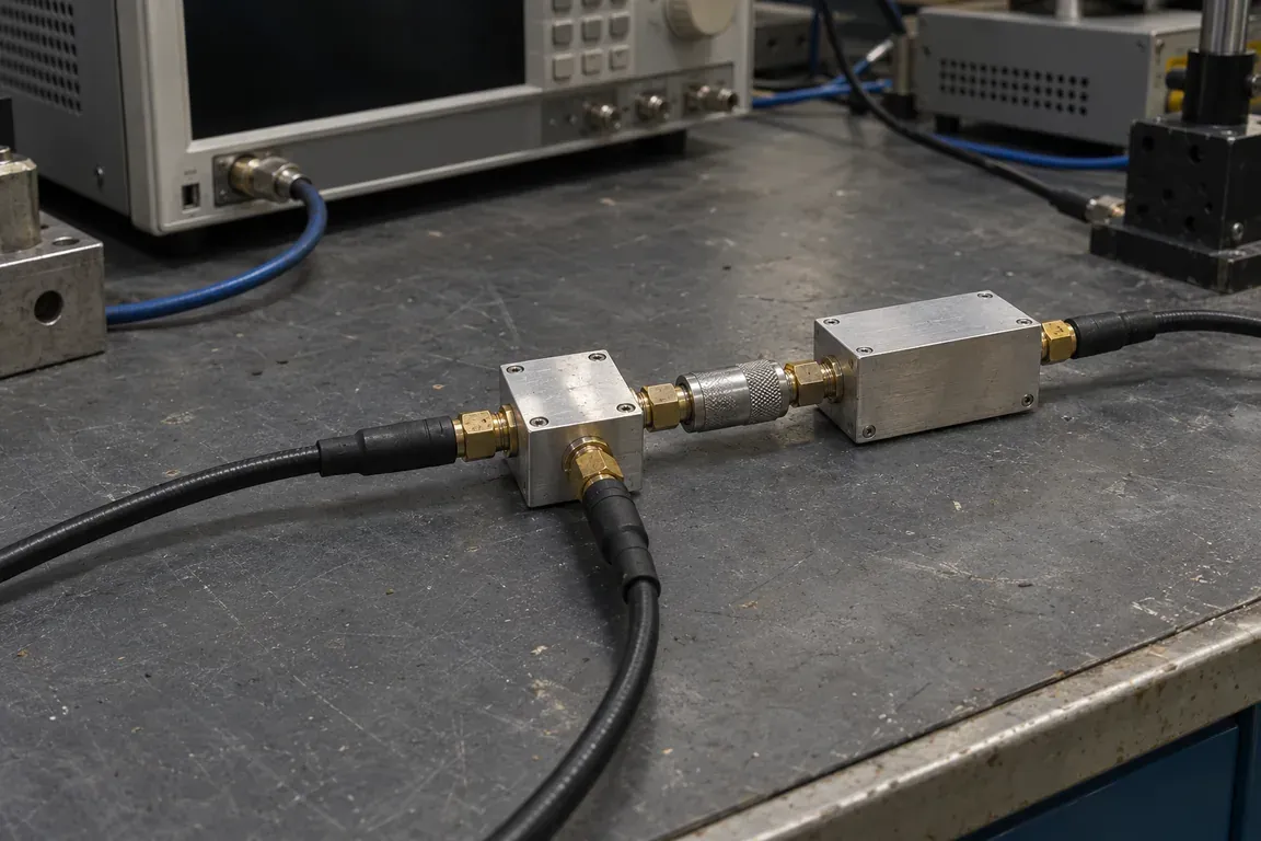
Connecting a conventional reflective filter directly to a mixer port rejects out-of-band mixing products back into the diodes and causes severe conversion-loss ripple across the passband. Before you waste board rework on a different mixer, lock your frequency plan and LO drive and run a three-state A/B fixture check at the IF port.
When a passive or nonlinear mixer sweeps smoothly into a broadband 50-ohm termination but develops amplitude ripple after an IF or RF filter is attached, out-of-band reflections from that filter are re-entering the mixer and remixing with local-oscillator harmonics. In Mini-Circuits’ 2 August 2015 downconverter example (ZFM-1H mixer with BLP-50 low-pass filter, 80–500 MHz RF, 120–540 MHz LO, 40 MHz IF), reflected sum energy produced up to 3 dB peak-to-peak conversion-loss ripple. Confirm the reflection mechanism with a same-conditions A/B cable-length check, then compare a resistive pad, a 50-ohm-terminated diplexer, and an absorptive filter against your loss and noise-figure budget.
This troubleshooting guide belongs to the RF signal chain section. Use RF, IF and LO explained for image and sum/difference frequency placement, and upconverter vs downconverter for filter ordering by conversion direction. Rewiring signals onto different physical pins stays on the mixer port-swap sheet, while datasheet leakage conventions belong on RF-to-IF isolation measurement conditions. Integrated assemblies that already enclose amplifiers and filters are covered on the frequency converter guide.
| Input or fixture parameter | Published reference or fixture rule | Why it matters for ripple diagnosis |
|---|---|---|
| Wanted product and sweep plan | Fixed IF (`fI = | fL − fR |
| Rejected out-of-band tone | Sum frequency fS = fL + fR in downconversion, or unused sideband/harmonics in upconversion |
A reflective filter returns fS into the mixer, where 2fL − (fL + fR) lands directly on the wanted IF fL − fR (Mini-Circuits, 2 Aug 2015). |
| Bench attenuator state | Factory conversion-loss setups often place a 10 dB pad at the I-port (at least 20 dB round-trip reflection suppression) | Removing the 10 dB pad in a real receiver to save signal level and noise figure exposes the mixer to stop-band reflections (Mini-Circuits, 2 Aug 2015). |
| Mixer-to-filter line length | Coaxial jumper or PCB trace electrical delay between mixer port and reflective filter | Adding line length increases the ripple frequency across the band and proves a standing-wave reflection loop (Marki Microwave, 4 Apr 2012). |
| LO drive at the mixer pin | Rated diode turn-on power at the physical LO port (e.g., +13 dBm across 16–30 GHz on HMC292LC3B, ADI EngineerZone, 13 Dec 2016) |
Under-driving the LO leaves mixer diodes partially off and causes broadband loss errors unrelated to filter reflections. |
| Reference plane and cable loss | Instrument port vs. mixer connector (e.g., 0.1–0.2 dB VNA cable offset in Copper Mountain’s setup; 5.5 dB uncalibrated 24 GHz cable loss in the ADI thread) | Separates flat fixture attenuation from frequency-periodic reflection ripple. |
Why adding a filter creates conversion-loss ripple on a smooth mixer
A double-balanced mixer is both a load and a source at all three ports. When used as a downconverter, its IF port outputs the desired difference frequency fI = |fL − fR| and the unwanted sum frequency fS = fL + fR at comparable amplitudes, alongside higher-order local-oscillator harmonics and intermodulation products.
Marki Microwave’s 4 April 2012 application note dispels the common assumption that conversion-loss ripple is caused simply by poor internal mixer VSWR. A standing wave requires two elements: a reflection at a load or source, and a transmission path delay for the reflected wave to rotate in phase. If internal mixer mismatch alone caused ripple, that ripple would appear even when all ports were terminated in broadband 50-ohm loads.
In the experiment reported in that Marki Microwave note, Ferenc Marki upconverted a 2 to 8 GHz input to 12 to 18 GHz using a 20 GHz LO:
- Wideband 50-ohm termination: Terminating the ports in broadband 50-ohm loads produced a smooth conversion-loss curve across the band.
- Reflective 18 GHz low-pass filter: Placing an 18 GHz low-pass filter on the output reflected the high-side mixing product back into the mixer, where it reconverted to the IF port and remixed into the desired output band as pronounced conversion-loss ripple.
- Added cable length: Inserting a length of coaxial cable between the mixer and the 18 GHz filter increased the frequency of the ripples across the sweep because the round-trip phase rotated more rapidly with frequency.
Mini-Circuits’ 2 August 2015 technical note gives the exact frequency arithmetic for a downconverter with a reflective low-pass or band-pass filter attached directly to the I-port:
- The primary downconverted signal at the I-port is the difference tone
fI = ±(fL − fR), accompanied by the sum tonefS = fL + fR. - A conventional reflective filter passes
fIand rejectsfSby reflecting it back into the mixer I-port. - Inside the mixer, the reflected sum tone recombines with the second harmonic of the local oscillator (
2fL) to generate a secondary IF tone:fI' = ±[2fL − (fL + fR)] = ±(fL − fR) - Because
fI'sits at the exact same frequency as the desired primary IFfI, the total output voltageVIFis the vector sum of the primary voltageVIF'and the secondary voltageVIF''separated by their phase angle φ. When RF and LO sweep together to hold the IF fixed,VIF',VIF'', and φ all vary with frequency, turning rotating phase into peaks and valleys of conversion loss—or, as Matthew Morgan notes in the 5 August 2015 Microwave Journal article, destructive interference “suck-outs” across broadband sweeps.
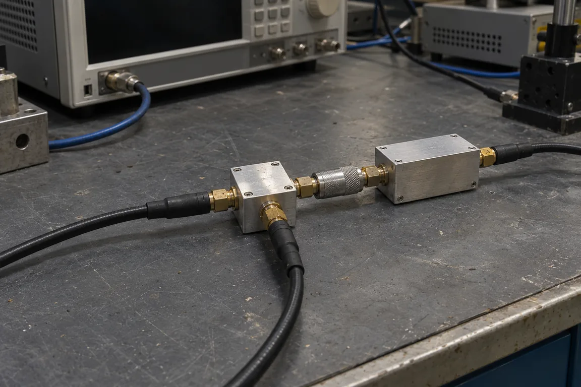
Why does datasheet characterization often look much flatter than your board? Mini-Circuits points out that bench conversion-loss setups commonly place a 10 dB resistive attenuator (pad) directly at the I-port ahead of the low-pass or band-pass filter. The outgoing sum tone loses 10 dB on the way to the filter and another 10 dB after reflecting back toward the mixer, keeping the reflected sum level at least 20 dB below the level leaving the I-port. In a receiver front end where a 10 dB IF pad degrades signal level and noise figure, connecting the filter directly to the I-port removes that 20 dB buffer.
Takeaway: Conversion-loss ripple after filter installation comes from out-of-band mixing products reflecting off the filter’s stop band, rotating in phase along the interconnecting line, and remixing onto the wanted frequency.
Rule out non-reflection causes before modifying the IF network
Not every bad conversion-loss trace is reflection ripple. Before changing filters or adding pads, verify that the fixture is actually turning the mixer on and measuring the intended product:
- LO drive threshold at the physical mixer port: In a 13 December 2016 Analog Devices EngineerZone support reply on the
HMC292LC3B, a user reported 30.5 dB conversion loss with a 24 GHz LO and 2 GHz IF. Analog Devices noted that for RF and IF return-loss and conversion operation on that part, the LO port requires at least +13 dBm across 16 to 30 GHz so the internal GaAs diodes turn on; without rated LO drive, the ports behave like an open or short. - Uncalibrated cable attenuation and reference plane offset: In the same EngineerZone thread, 5.5 dB of coaxial cable loss at 24 GHz between the DUT and the analyzer had not been normalized out. Similarly, Copper Mountain Technologies’ 19 April 2018 characterization note records a 0.1 to 0.2 dB power drop between the VNA port reference plane and the mixer input due to cable attenuation.
- Board launch, rework heat, and ESD: The EngineerZone reply also flagged non-evaluation CPW launch geometry (missing dual via rows on
Arlon 25FR), conversion direction confusion (upconversion vs. downconversion), and potential reflow/ESD damage—and replacing the IC resolved that user’s 30.5 dB loss fault.
If conversion loss is uniformly high by 10 to 20 dB across the whole band, inspect LO power at the mixer pin, cable loss, and device integrity first. If nominal conversion loss is present but oscillates cyclically across frequency when the filter is attached, proceed to the A/B fixture checklist below.
The same-conditions A/B fixture checklist and test record
To prove that out-of-band filter reflections explain the ripple—and to measure whether a candidate remedy stays within your system gain and noise budget—keep the frequency plan, LO drive, and RF input power locked while changing only the IF port termination state.
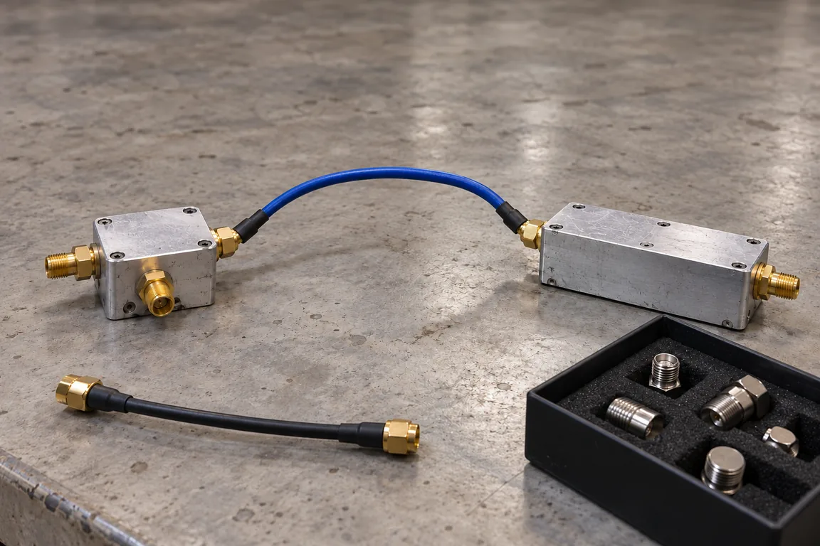
Run these four fixture states in order without altering generator power or calibration:
- Run A — Broadband 50-ohm reference (or 10 dB pad reference): Measure conversion loss
Lconv = PRF − PIF(in dB, withPRFandPIFin dBm at the stated reference planes) into a broadband 50-ohm analyzer input or through a calibrated 10 dB pad ahead of the filter. Record baseline conversion loss and baseline peak-to-peak flatness. - Run B — Direct reflective filter: Remove the reference pad and connect the intended low-pass or band-pass filter at the normal fixture spacing
L1. Record peak-to-peak conversion-loss ripple and the frequency spacing between adjacent ripple peaks. - Run C — Added transmission-line delay (
L2 > L1): Insert a known extra length of 50-ohm coaxial cable or airline between the mixer port and the same reflective filter. Following Marki Microwave’s 2012 test, if the ripple period compresses (more ripple cycles across the same sweep span), the ripple is confirmed as a standing-wave reflection between the filter stop band and the mixer port. - Run D — Candidate remedy installed: Replace the direct reflective filter with your candidate remedy (fixed pad + filter, 50-ohm-terminated diplexer, or constant-impedance / reflectionless filter) at spacing
L1, and re-check atL2to confirm line-length insensitivity.
Copy the blank record below into your bench log. All measurement cells are intentionally left blank (Unknown / verify on the unit) until populated from your hardware under test.
| Fixture record field | Fixed condition / definition | Run A: 50 Ω or 10 dB pad baseline | Run B: Direct filter (length L1) | Run C: Direct filter + extra cable (L2) | Run D: Candidate remedy installed |
|---|---|---|---|---|---|
| Mixer model, topology, and datasheet revision | Record bare passive diode, MMIC, or active topology | ||||
| Frequency plan (RF range, LO range, IF range) | State fixed-IF swept RF/LO or fixed-LO swept RF/IF | ||||
Rejected out-of-band product (fS, 2fL ± fR, image) |
Frequency span of the tone hitting the filter stop band | ||||
| LO drive power and RF input power at mixer pins | Keep identical across Runs A–D; verify linear RF range | ||||
Interconnect between mixer port and filter (L1, L2) |
Coaxial cable / PCB trace length and connector type | ||||
| Filter / termination network configuration | Model, center/cutoff frequency, pad dB, or diplexer load | ||||
| Reference plane and cable-loss correction | Instrument port or mixer connector; de-embedded offset (dB) | ||||
Midband conversion loss Lconv = PRF − PIF (dB) |
Include added pad or filter insertion loss at wanted IF | ||||
| Peak-to-peak conversion-loss ripple across band (dB p-p) | Maximum minus minimum Lconv over the swept passband |
||||
Ripple peak-to-peak frequency spacing (Δf, MHz) |
Checks whether extra length L2 increases ripple frequency |
||||
Two-tone IIP3 or in-band spur check (optional, dBm / dBc) |
Recheck if multi-carrier intermodulation limits dynamic range |
Takeaway: If switching from Run B (L1) to Run C (L2) changes the number of ripple cycles across the band while LO drive and levels are untouched, stop debugging the mixer core and fix the out-of-band port termination.
Comparing the three remedies: resistive pad, terminated diplexer, and absorptive filter
Once Run B and Run C confirm reflection-induced ripple, the choice of remedy is a trade-off between return-loss improvement (2× any series attenuation), added passband insertion loss and noise figure, stop-band absorption bandwidth, and board area.
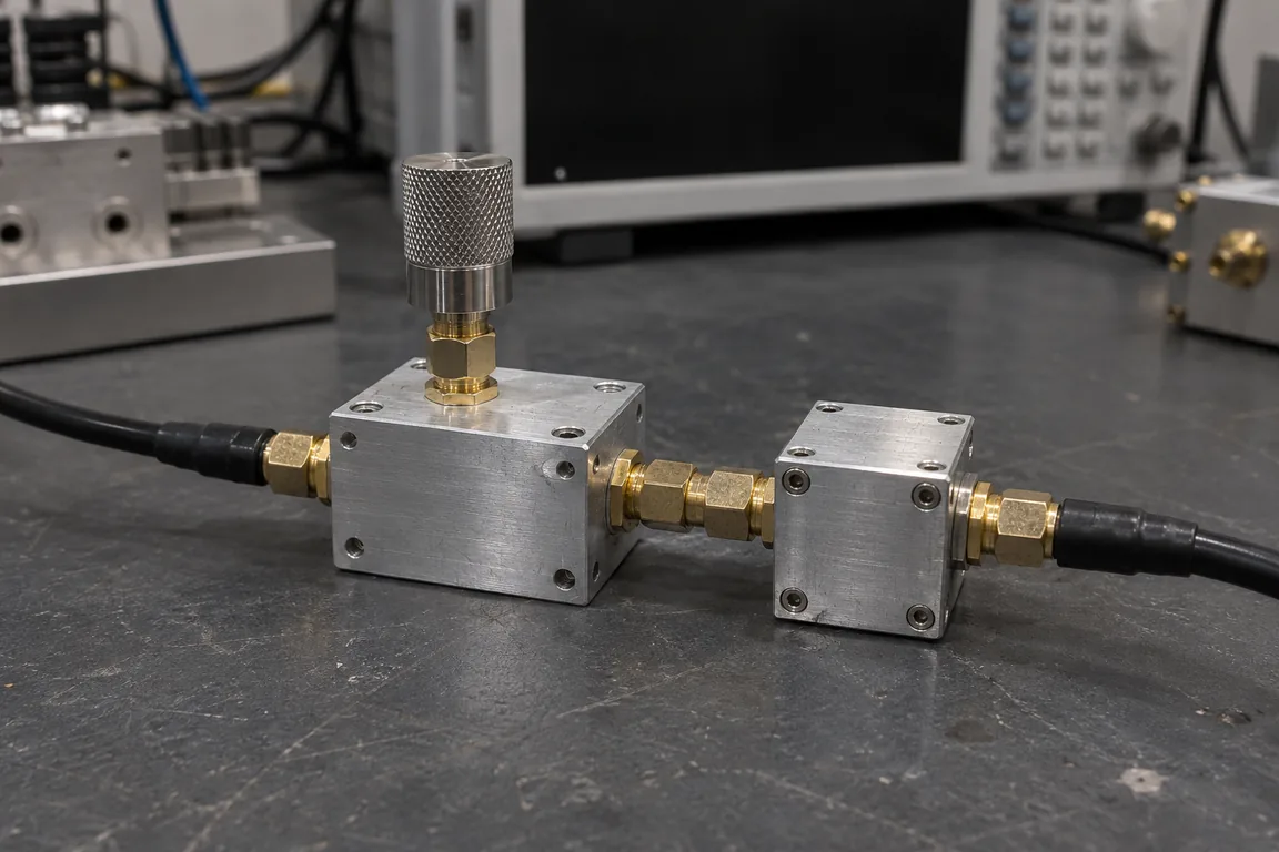
The matrix below compiles the mechanism, published manufacturer benchmarks, and system trade-offs from Marki Microwave (2012), Mini-Circuits (2015), Mini-Circuits AN75-007, and Microwave Journal (2015). Published numbers apply strictly to the vendor test circuits named.
| Decision factor | Remedy 1: Resistive attenuator pad + conventional filter | Remedy 2: Diplexer with unused port terminated in 50 Ω | Remedy 3: Constant-impedance or reflectionless (absorptive) filter |
|---|---|---|---|
How it handles out-of-band mixing products (fS, harmonics) |
The conventional filter still reflects the stop-band tone, but the resistive pad attenuates both the forward wave and the reflected wave. | Frequency-selective crossover routes the desired IF to one port and diverts the unwanted high-pass or low-pass band into an external 50-ohm load (Marki Microwave, 2012). | Internal resistive terminations absorb stop-band energy inside the filter network rather than reflecting it back to the source (Mini-Circuits AN75-007). |
| Reflection suppression / stop-band return loss | Round-trip reflection drops by 2× the pad value (a 10 dB pad suppresses reflected sum power by at least 20 dB, Mini-Circuits, 2 Aug 2015). |
Absorbs out-of-band energy across the terminated branch; AN75-007 notes that reflections can still occur from impedance mismatch in the crossover transition band. | PIF-40 constant-impedance IF bandpass example: typical stop-band return loss is 18 dB up to 10× center frequency (13 dB measured up to 1040 MHz in the test). AN75-007 reflectionless test at 2 GHz: reflected tone dropped by more than 30 dB, from −34.35 dBm to −66.12 dBm. |
| Passband insertion loss & noise-figure penalty | High penalty: Every dB of pad attenuation adds directly to conversion loss and degrades IF noise figure and SNR (Mini-Circuits, 2 Aug 2015; AN75-007). | Low passband penalty: Avoids broadband resistive pad loss in the desired IF path; only the diplexer passband insertion loss applies. | Low passband penalty: Avoids brute-force pad attenuation while maintaining a 50-ohm match in both passband and stop band (Microwave Journal, 5 Aug 2015). |
| Published ripple or linearity benchmark (vendor examples only) | Bench reference in Mini-Circuits (2 Aug 2015) uses a 10 dB I-port pad to establish broadband 50-ohm termination during factory conversion-loss tests. | Listed by Marki Microwave (4 Apr 2012) as a primary fix when an 18 GHz low-pass filter caused upconversion ripple on a 2–8 GHz to 12–18 GHz (20 GHz LO) setup. | In Mini-Circuits (2 Aug 2015), replacing a reflective BLP-50 low-pass filter on a ZFM-1H mixer (RF 80–500 MHz, LO 120–540 MHz, IF 40 MHz, sum 200–1040 MHz) with a PIF-40 reduced ripple from up to 3 dB p-p to within 0.3 dB p-p. |
| Footprint, bandwidth, and cascading limits | Smallest added footprint (one surface-mount or coaxial pad), works over the full DC-to-microwave rating of the resistor pad. | Demanding on board space because it requires two filter branches plus an external 50-ohm termination (AN75-007). | Compact (e.g., Mini-Circuits’ 2015 NR-series release used 3 × 3 mm GaAs IPD QFN packages covering DC to 21 GHz) and can be cascaded or paired with conventional filters without line-length ripple (Microwave Journal, 5 Aug 2015). |
| When to select in your signal chain | Bench characterization fixtures, high-level transmit paths, or IF stages with enough conversion gain and SNR margin to absorb the pad loss. | Fixed-IF or non-overlapping bands where desired and sum products sit cleanly on opposite sides of the diplexer crossover and board area allows a terminated third port. | Noise-sensitive receivers, broadband sweeps, or compact layouts where pad loss is unacceptable and mixer-to-filter trace length cannot be tuned by hand. |
Why quadrature-hybrid balanced filters are a separate, bandwidth-limited case
Both Mini-Circuits AN75-007 and Microwave Journal (5 August 2015) note a fourth traditional approach: placing 90-degree quadrature hybrids at the input and output of a matched pair of conventional filters so reflected stop-band energy routes to the hybrid isolation ports. While that buffers the mixer within the hybrid operating band, the overall bandwidth is restricted by the quadrature hybrids, making the balanced-filter approach unsuitable for broadband multi-octave stop-band termination.
Checking two-tone intermodulation alongside conversion-loss ripple
Reflections from a conventional IF filter do not only distort single-tone conversion flatness. As Mini-Circuits’ 2 August 2015 note explains, when two RF carriers (fRF1 and fRF2) enter the mixer, third-order intermodulation products at fLO ± (2fRF1 − fRF2) and fLO ± (2fRF2 − fRF1) sit at the same spacing from the desired IF as the RF carriers. If sum-frequency products reflect off a conventional IF filter and re-enter the mixer, they mix with the second harmonic of the LO and add vectorially to the primary IF and its intermodulation tones—generating additional “family members” of in-band spurs (AN75-007). When your system specification includes two-tone IIP3 or spurious-free dynamic range (SFDR), record the two-tone spur delta in the last row of the A/B fixture sheet above.
Boundaries: what manufacturer examples do and do not establish
Keep the published numbers attached to their exact test circuits:
- The 3 dB p-p to 0.3 dB p-p ripple reduction in Mini-Circuits’ 2 August 2015 note was measured on a
ZFM-1Hmixer with anMCL BLP-50low-pass filter versus aPIF-40constant-impedance bandpass filter at a 40 MHz IF (RF = 80 to 500 MHz, LO = 120 to 540 MHz, sum = 200 to 1040 MHz, where thePIF-40provided at least 14 dB sum attenuation and 13 dB return loss up to 1040 MHz). It is not a guaranteed ripple figure for another mixer, another IF, or a sum frequency beyond the filter’s rated absorptive stop band. - The −34.35 dBm to −66.12 dBm (more than 30 dB) reflection reduction in
AN75-007was measured at a single 2 GHz reflected tone in Mini-Circuits’ proof-of-concept circuit. - Marki Microwave’s 4 April 2012 note establishes the standing-wave mechanism on a 2–8 GHz to 12–18 GHz upconversion with a 20 GHz LO and an 18 GHz low-pass filter, and points to absorptive (
WAVEFADE) filters or 50-ohm-terminated diplexers as remedies without promising a universal dB improvement.
Method and sources
Updated 17 October 2026. This guide synthesizes published application notes from Marki Microwave (4 April 2012), Mini-Circuits (2 August 2015), Mini-Circuits AN75-007, Microwave Journal (5 August 2015), Copper Mountain Technologies (19 April 2018), and Analog Devices EngineerZone (December 2016). The community question that motivated this troubleshooting record (r/rfelectronics, “RF mixers and reflections from filtering”, 31 October 2019) was verified from its indexed search excerpt because direct forum retrieval returned HTTP 403.
No hardware was measured by this site, and all cells in the A/B fixture record remain blank for the reader’s bench entries. Corrections and source updates follow our editorial policy.
Frequently asked questions
Does bad mixer VSWR alone cause conversion-loss ripple across frequency?
No. Marki Microwave's 4 April 2012 application note explains that internal mixer VSWR by itself does not create swept conversion-loss ripple without an external reflection and a transmission path delay to form a standing wave. In Ferenc Marki's 2–8 GHz to 12–18 GHz upconversion test with a 20 GHz LO, wideband 50-ohm loads produced a smooth trace while an 18 GHz reflective low-pass filter caused significant ripple.
Why does a bench test with a 10 dB pad hide IF filter reflection ripple?
Mini-Circuits' 2 August 2015 technical note explains that a 10 dB attenuator placed at the mixer I-port ahead of a low-pass or band-pass filter attenuates the outgoing sum product by 10 dB and the reflected sum product by another 10 dB, keeping the returning wave at least 20 dB down. Removing that 10 dB pad in a receiver to preserve signal level and noise figure exposes the mixer port to the full stop-band reflection.
When should you check LO drive and cable calibration before blaming IF filter reflections?
When conversion loss is degraded across the entire band rather than rippling periodically with line length. In a 13 December 2016 Analog Devices EngineerZone reply on the HMC292LC3B, a reported 30.5 dB conversion loss was traced to device handling/replacement, an uncalibrated 5.5 dB cable loss at 24 GHz, and the requirement for at least +13 dBm of LO drive across 16–30 GHz to turn on the mixer diodes.
Sources
- Does Mixer VSWR Matter? (4 April 2012) — Marki Microwave Accessed October 11, 2026.
- Constant-Impedance IF Band-pass Filters Improve Circuits Performance (2 August 2015) — Mini-Circuits Accessed October 17, 2026.
- AN75-007: Pairing Mixers with Reflectionless Filters to Improve System Performance — Mini-Circuits Accessed October 17, 2026.
- Reflectionless Filters Improve Linearity and Dynamic Range (5 August 2015) — Microwave Journal Accessed October 17, 2026.
- RF Mixer Characterization (19 April 2018) — Copper Mountain Technologies Accessed October 17, 2026.
- HMC292ALC3B conversion loss problem (EngineerZone, 8–20 December 2016) — Analog Devices EngineerZone Accessed October 11, 2026.