Direct answer
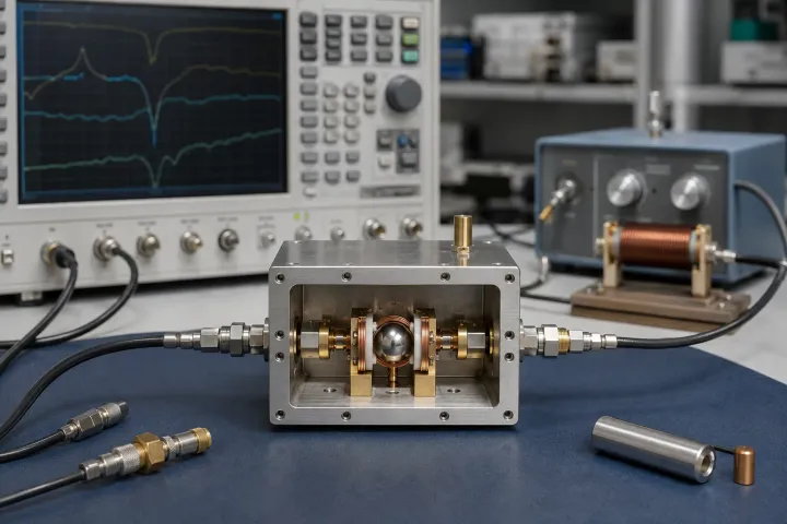
Selecting a YIG sphere by diameter alone causes below-resonance spin-wave failure, spurious Walker modes, and thermal drift. Single-crystal yttrium iron garnet (Y3Fe5O12) spheres tune linearly at 2.80 MHz/Oe via Kittel ferrimagnetic resonance, where sub-micron polish (ΔH <= 0.25 Oe) yields high unloaded Q. Specify pure YIG above 2 GHz, Ga-YIG for UHF/L-band, and align the zero-drift axis.
Key takeaways
- Isotropic spherical demagnetization factors (Nx = Ny = Nz = 1/3) cancel first-order shape magnetization from the Kittel (1,1,0) mode, setting resonant frequency to f_0 = γ × (H_0 + H_a) with γ = 2.80 MHz/Oe.
- Pure yttrium iron garnet (4πMs = 1,780 G, Tc = 280 °C) hits spin-wave coincidence limiting below 1.8–2.0 GHz; UHF and L-band resonators (0.4–2.0 GHz) require gallium-doped Ga-YIG grades (4πMs = 400–1,200 G).
- Intrinsic magnetic unloaded quality factor follows Q_m ≈ f_0 / (γ × ΔH); an optical-finish sphere (Ra <= 0.05 µm, ΔH = 0.25 Oe) reaches Q_m = 14,286 at 10 GHz, reducing oscillator phase noise by 20·log10(Q_L).
- Orienting the sphere at θ ≈ 29.7° from the [100] hard axis in the (110) plane zeroes first-order magnetocrystalline anisotropy drift (∂H_a/∂T ≈ 0) on a Beryllium Oxide (BeO) or single-crystal sapphire arbor rod.
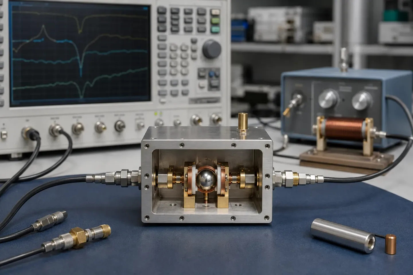
Selecting a YIG sphere by physical diameter or nominal frequency range alone causes severe below-resonance spin-wave insertion loss, spurious passband rejection notches, and costly local-oscillator rework. Before specifying a ferrimagnetic resonator or diagnosing phase-noise degradation in a broadband microwave assembly, match the crystal’s saturation magnetization (4πMs), ferromagnetic resonance (FMR) linewidth (ΔH), diameter-to-wavelength ratio, and (110)-plane crystallographic mounting angle to your operating band.
A single-crystal yttrium iron garnet (Y3Fe5O12) sphere is an optical-finish ferrimagnetic resonator whose isotropic shape demagnetization factors (Nx = Ny = Nz = 1/3) cancel first-order saturation magnetization from the Kittel (1,1,0) uniform-precession mode, setting resonant frequency to f_0 = γ × (H_0 + H_a) with γ = 2.80 MHz/Oe. Pure YIG (4πMs = 1,780 G, Tc = 280 °C) supports fundamental operation from 2.0 GHz to 40+ GHz with unloaded Q_u exceeding 9,000 at X-band when polished to Ra <= 0.05 µm (ΔH <= 0.25 Oe), whereas UHF and L-band operation (400 MHz to 2.0 GHz) requires gallium-substituted Ga-YIG (4πMs = 400–1,200 G) to avoid Suhl first-order spin-wave coincidence limiting.
This resonator reference belongs to the YIG technology hub and underpins device-level specifications across the RF and microwave components directory. For an introductory overview of magnetic versus geometric tuning, start with what YIG is and why microwave designs use it. For external dual-coil current drivers and negative-resistance sustaining loops, see how YIG oscillators work, alongside the module-level selection guides for YIG oscillators and YIG filters.
| Resonator Parameter | Symbol & Units | Pure YIG (Y3Fe5O12) Benchmark |
Gallium-Doped Ga-YIG (Y3Fe5-xGaxO12) |
Primary Circuit Consequence |
|---|---|---|---|---|
| Room-temperature saturation magnetization | 4πMs (Gauss / mT) |
1,780 G (178 mT) at 25 °C (Matesy) |
400 G to 1,200 G (40–120 mT) across doped grades |
Sets lower coincidence cutoff frequency f_min and maximum RF drive threshold before spin-wave limiting |
| Lower spin-wave coincidence cutoff | f_min (GHz) |
1.80 to 2.00 GHz (f_sat = 1.66 GHz) |
0.45 to 1.40 GHz (scales with (1/3)·γ·4πMs) |
Operating below f_min couples into the f_0 / 2 spin-wave manifold, collapsing 1 dB compression to -15 dBm (Micro Lambda YTF) |
| Curie temperature | Tc (°C / K) |
280 °C (553–560 K) |
130 °C to 215 °C (403–488 K) |
Lower Tc in Ga-YIG increases thermal magnetization sensitivity near +85 °C PTC heater setpoints |
X-band FMR 3 dB linewidth |
ΔH (Oe) |
0.20 to 0.35 Oe at 10 GHz, 295 K (Krupka et al., 2017) |
0.35 to 1.25 Oe (broadened by cation disorder) |
Governs unloaded quality factor Q_m ≈ f_0 / (γ × ΔH); doubling ΔH degrades oscillator phase noise by 6.0 dB |
| Sphere diameter & surface finish | d_s (mm / mils), Ra (µm) |
0.20–0.50 mm (8–20 mils), Ra <= 0.05 µm optical finish |
0.30–0.60 mm (12–24 mils), Ra <= 0.05 µm |
Keeps d_s < λ_0 / 20 at 18–40 GHz to suppress spurious Walker modes; optical polish prevents two-magnon pit scattering |
| Zero-drift crystal axis & arbor rod | θ_0 in (110) plane, rod k / tan δ |
θ ≈ 29.7° (27°–30°) from [100] on BeO (260 W/m·K) or Sapphire (tan δ < 0.00005) |
θ ≈ 29.7° in (110) plane on BeO, Sapphire, or 99.6% Alumina |
Zeroes first-order cubic anisotropy thermal slope (∂H_a/∂T ≈ 0) while conducting heat from the PTC heater (Micro Lambda YTO) |
Single-Crystal Y3Fe5O12 Sublattice Physics and Kittel (1,1,0) Sphere Resonance
Yttrium iron garnet (Y3Fe5O12) crystallizes in the body-centered cubic space group Ia-3d with a lattice constant a = 12.376 Å containing eight formula units (160 atoms) per unit cell. Unlike metallic ferromagnetic alloys such as permalloy or cobalt-iron—which conduct electricity and suffer severe skin-depth eddy-current damping at gigahertz frequencies—single-crystal YIG is a wide-bandgap electrical insulator with bulk DC resistivity exceeding 10^12 Ω·cm and a microwave dielectric loss tangent tan δ < 0.0002. Electromagnetic fields penetrate the entire volume of the crystal sphere without ohmic eddy-current dissipation.
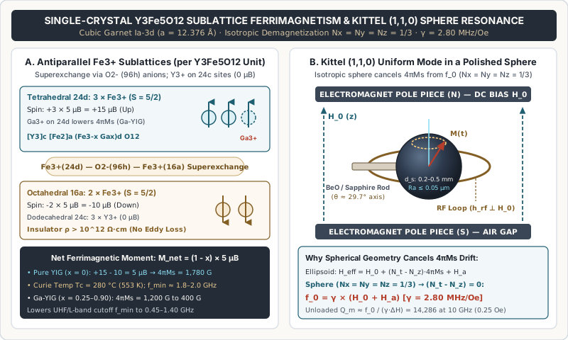
The magnetic behavior of Y3Fe5O12 arises from antiparallel sublattice ferrimagnetism mediated by oxygen (O2-) superexchange rather than simple ferromagnetism:
- Dodecahedral
24csites ([Y3]^c): Occupied by three non-magnetic trivalent yttrium ions (Y3+, electronic configuration4d^0, zero net spin moment0 μB). - Tetrahedral
24dsites ((Fe3)^d): Occupied by three trivalent iron ions (Fe3+, high-spin3d^5configuration with spin quantum numberS = 5/2and zero orbital angular momentumL = 0, contributing5 Bohr magnetons/5 μBper ion). The three tetrahedralFe3+ions align parallel to one another for a sublattice contribution of+3 × 5 μB = +15 μBper formula unit. - Octahedral
16asites ([Fe2]^a): Occupied by two trivalent iron ions (Fe3+,S = 5/2,5 μBper ion) coupled antiparallel to the tetrahedral24dsublattice across intervening96hoxygen anions (Fe3+(24d)—O2-—Fe3+(16a)bond angles near125°), yielding-2 × 5 μB = -10 μBper formula unit.
Subtracting the two opposing iron sublattices leaves an uncompensated net ferrimagnetic moment of +15 μB - 10 μB = 5 μB per Y3Fe5O12 formula unit. At room temperature (25 °C / 298 K), this net moment produces a saturation magnetization of 4πMs = 1,780 Gauss (178 mT) and a Curie temperature Tc ≈ 280 °C (553–560 K). Equally important for microwave resonator Q, because Fe3+ is an S-state ion (L = 0), spin-orbit coupling to the crystal lattice is exceptionally weak, giving flux-grown Y3Fe5O12 the narrowest intrinsic spin-lattice relaxation linewidth of any practical microwave ferrite (Krupka et al., 2017).
Why a Sphere? Cancelling Shape Demagnetization in Kittel’s Equation
When a ferrimagnetic ellipsoid with principal demagnetization factors Nx, Ny, and Nz (where Nx + Ny + Nz = 1 in CGS units) is saturated along the z-axis by a uniform external static magnetic field H_0, the general Kittel ferromagnetic resonance equation for the uniform-precession (1,1,0) mode is:
f_0 = γ × sqrt( [H_0 + (Nx - Nz) × 4πMs + H_ax] × [H_0 + (Ny - Nz) × 4πMs + H_ay] )
Here γ = 2.80 MHz/Oe (2.80 GHz/kG or 28.0 GHz/T) is the gyromagnetic ratio of the electron spin, and H_ax, H_ay represent the effective cubic magnetocrystalline anisotropy fields along the transverse axes. In a non-spherical sample, the shape-demagnetization differences (Nx - Nz) and (Ny - Nz) are non-zero:
- In-plane magnetized thin film or slab (
Nx = Nz = 0, Ny = 1): The Kittel resonance becomesf_0 = γ × sqrt( H_0 × (H_0 + 4πMs) )(takingH_a ≈ 0). Because4πMssits directly inside the square root, the steep thermal slope of saturation magnetization (∂(4πMs)/∂T ≈ -3.6 Gauss/°Cfor pure YIG near25 °C) pulls the resonant frequency by several megahertz per degree Celsius. - Perpendicularly magnetized disk or rod (
Nz = 1, Nx = Ny = 0): The resonance shifts tof_0 = γ × (H_0 - 4πMs + H_a), directly coupling-γ × 4πMs(-4,984 MHzfor pure YIG) and its full temperature drift (-10.1 MHz/°C) into the oscillator or filter center frequency. Furthermore, sharp corners on cubes, cylinders, or disks create non-uniform internal demagnetizing fields near the edges, exciting dense clusters of spurious magnetostatic modes.
Grinding and polishing the single crystal into a precision sphere makes the directional shape demagnetization factors identical along all three Cartesian axes:
Nx = Ny = Nz = 1/3
Substituting Nx = Ny = Nz = 1/3 into Kittel’s equation forces (Nx - Nz) = 0 and (Ny - Nz) = 0, eliminating 4πMs completely from the first-order uniform-precession resonant frequency:
f_0 = γ × (H_0 + H_a)
Inside a saturated sphere, the internal static magnetic field is H_i = H_0 - (1/3) × 4πMs, while the transverse RF demagnetizing field adds +(1/3) × 4πMs back to the precessional restoring torque. The two (1/3) × 4πMs contributions cancel identically. Consequently, the resonant frequency f_0 of an isotropic YIG sphere tracks the external bias field H_0 with a constant tuning slope of 2.80 MHz/Oe across multi-octave microwave spans, and temperature variations in 4πMs do not pull the first-order center frequency (Krupka et al., 2017 PDF).
Takeaway: A spherical resonator (Nx = Ny = Nz = 1/3) is mandatory because it cancels saturation magnetization 4πMs and its -3.6 G/°C thermal slope from Kittel’s uniform-precession frequency equation f_0 = γ × (H_0 + H_a).
Pure YIG vs. Gallium-Doped Ga-YIG (4πMs): Spin-Wave Coincidence and Lower Cutoff (f_min)
Although 4πMs cancels out of the Kittel tuning equation f_0 = γ × (H_0 + H_a) above resonance, saturation magnetization strictly governs the lowest usable operating frequency (f_min) and the nonlinear RF power-handling threshold of every YIG sphere. Two physical boundaries set the lower frequency cutoff of a spherical ferrimagnetic resonator:
1. Internal Magnetic Saturation Boundary (f_sat_min)
For the Kittel (1,1,0) uniform precession mode to exist without magnetic domain break-up, the external DC bias field H_0 must overcome the sphere’s internal demagnetizing field (1/3) × 4πMs so that the internal static field H_i remains positive throughout the crystal volume:
H_i = H_0 - (1/3) × 4πMs > 0 → H_0_min = (1/3) × 4πMs
Multiplying by γ = 2.80 MHz/Oe (with H_a ≈ 0) yields the absolute minimum saturation resonance frequency f_sat_min:
f_sat_min = (1/3) × γ × 4πMs
For pure Y3Fe5O12 (4πMs = 1,780 Gauss):
H_0_min = (1/3) × 1,780 Oe = 593.3 Oef_sat_min = 2.80 MHz/Oe × 593.3 Oe = 1,661 MHz(1.66 GHz)
Below 1.66 GHz, a pure YIG sphere cannot remain magnetically saturated at 25 °C; it breaks into multi-domain walls that absorb RF energy and destroy resonator Q.
2. Suhl First-Order Spin-Wave Coincidence Limiting (f_coincidence)
Even above f_sat_min = 1.66 GHz, a second mechanism restricts pure YIG in low-loss filters and high-power oscillators: Suhl’s first-order nonlinear instability (coincidence limiting). In addition to the spatially uniform (1,1,0) Kittel mode (k ≈ 0), the ferrimagnetic lattice supports a continuous manifold of short-wavelength spin waves (magnons) with wavevector k propagating at angle θ_k relative to H_0. The spin-wave dispersion manifold spans from a lower boundary (θ_k = 0, parallel propagation):
f_sw_min = γ × H_i = f_0 - (1/3) × γ × 4πMs
up to an upper manifold boundary (θ_k = 90°, perpendicular propagation):
f_sw_max = γ × sqrt( H_i × (H_i + 4πMs) )
As reported in Micro Lambda Wireless’s YIG-Tuned Filter technology reference, whenever half of the RF signal frequency (f_0 / 2) lies inside or above the lower edge of the spin-wave manifold (f_0 / 2 >= f_sw_min), a uniform-precession magnon at f_0 can parametrically split into a pair of degenerate half-frequency spin waves (f_k = f_0 / 2 with equal and opposite wavevectors +k and -k). Setting f_0 / 2 = f_0 - (1/3) × γ × 4πMs defines the Suhl coincidence threshold frequency:
f_coincidence = (2/3) × γ × 4πMs
For pure YIG (4πMs = 1,780 G), f_coincidence = (2/3) × 2.80 MHz/Oe × 1,780 G = 3,323 MHz (3.32 GHz). Between 1.66 GHz and 3.32 GHz, the f_0 / 2 spin-wave manifold is degenerate with the main resonance, and the critical RF magnetic field threshold h_crit ∝ ΔH × sqrt(ΔH_k) drops sharply. Near the bottom of this zone (< 1.80 to 2.00 GHz), three-magnon and two-magnon couplings spike insertion loss and collapse the filter 1 dB compression (limiting) level from +10 dBm down to -15 dBm to -25 dBm. Consequently, commercial pure-YIG oscillators and filters specify a practical lower frequency limit of f_min ≈ 2.0 GHz (Micro Lambda Wideband YTO Catalog).
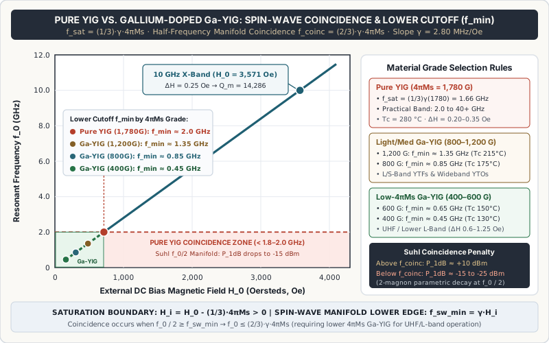
How Tetrahedral Gallium Substitution (Ga-YIG, Y3Fe5-xGaxO12) Enables UHF and L-Band Tuning
To build magnetically tuned oscillators and tracking preselectors operating between 400 MHz and 2.0 GHz (UHF and L-band), crystal growers lower 4πMs by substituting non-magnetic trivalent gallium ions (Ga3+, ionic radius 0.47 Å)—or combined aluminum/gadolinium/indium dopants—into the garnet melt during high-temperature PbO-PbF2-B2O3 flux growth (Matesy YIG Cubes and Spheres).
Because Ga3+ has a smaller ionic radius than Fe3+ (0.64 Å octahedral / 0.49 Å tetrahedral), Ga3+ strongly prefers to occupy the tetrahedral 24d iron sublattice:
[Y3]^c [Fe2]^a (Fe_{3-x} Ga_x)^d O12
Recall that the tetrahedral 24d sublattice carries the majority spin moment (+15 μB), opposing the octahedral 16a sublattice (-10 μB). Replacing x magnetic Fe3+ ions per formula unit on the 24d sublattice with non-magnetic Ga3+ (0 μB) directly reduces the net ferrimagnetic moment:
M_net(x) ≈ [ (3 - x) - 2 ] × 5 μB = (1 - x) × 5 μB
By controlling the gallium stoichiometry x between 0.20 and 0.95, crystal manufacturers produce standardized Ga-YIG grades with 4πMs tailored to the required lower cutoff frequency f_min:
| Material Composition & Grade | Room-Temp 4πMs (25 °C) |
Saturation Cutoff f_sat_min = (1/3)γ(4πMs) |
Practical Lower Cutoff f_min |
Curie Temperature Tc |
Typical Linewidth ΔH (25 °C) |
Primary Microwave Application Band |
|---|---|---|---|---|---|---|
Pure YIG (Y3Fe5O12, x = 0) |
1,780 G (178 mT) |
1.66 GHz (593 Oe) |
1.80 – 2.00 GHz |
280 °C (553 K) |
0.20 – 0.35 Oe (at 10 GHz) |
S, C, X, Ku, K, and Ka-band YTOs & YTFs (2.0 to 40+ GHz) |
Lightly Doped Ga-YIG (x ≈ 0.30) |
1,200 G (120 mT) |
1.12 GHz (400 Oe) |
1.30 – 1.40 GHz |
215 °C (488 K) |
0.35 – 0.50 Oe (at 6 GHz) |
Upper L-band and wideband S/C-band (1.4 to 12 GHz) |
Medium Doped Ga-YIG (x ≈ 0.50) |
800 G (80 mT) |
0.75 GHz (267 Oe) |
0.85 – 0.95 GHz |
175 °C (448 K) |
0.45 – 0.70 Oe (at 4 GHz) |
L-band & S-band oscillators (1.0 to 4.0 GHz) and preselectors |
Heavily Doped Ga-YIG (x ≈ 0.68) |
600 G (60 mT) |
0.56 GHz (200 Oe) |
0.65 – 0.70 GHz |
150 °C (423 K) |
0.60 – 0.90 Oe (at 3 GHz) |
Upper UHF and L-band (0.70 to 3.0 GHz) |
Ultra-Low-4πMs Ga-YIG (x ≈ 0.85) |
400 G (40 mT) |
0.37 GHz (133 Oe) |
0.45 – 0.50 GHz |
130 °C (403 K) |
0.80 – 1.25 Oe (at 2 GHz) |
UHF band (0.45 to 2.0 GHz wideband YTOs & tracking filters) |
Why You Should Never Specify Ga-YIG When Pure YIG Covers the Band
While a 400 G or 800 G Ga-YIG sphere is mandatory for 0.5–2.0 GHz or 1.0–4.0 GHz operation, substituting gallium carries three unavoidable physical penalties above 2.0 GHz:
- Collapsed Curie Temperature (
Tc): Diluting magneticFe3+ions withGa3+breaks a fraction of theFe(24d)—O2-—Fe(16a)superexchange linkages, droppingTcfrom280 °Cin pure YIG down to130 °Cin400 GGa-YIG. Because internal resonator heaters regulate the sphere at+80 °C to +95 °C(above the+85 °Cmilitary ambient limit), a400 GGa-YIGsphere operates within35–50 °Cof its Curie point, where4πMsand coupling bandwidth drop steeply. - Reduced Coupling Bandwidth (
BW_3dB ∝ V_s × 4πMs): The magnetic coupling coefficient between a YIG sphere of volumeV_sand an RF loop of diameterd_loopis directly proportional to4πMs. Lowering4πMsfrom1,780 Gto600 Greduces external loop coupling by nearly3×, requiring either larger spheres or tighter loop clearances to achieve a given filter passband width. - Broader FMR Linewidth (
ΔH): Random statistical distribution ofGa3+ions across24dtetrahedral sites creates localized spin-canting and magnetocrystalline fluctuations, broadeningΔHfrom0.25 Oe(pure YIG) to0.60–1.25 Oe(Ga-YIG).
Takeaway: Specify pure YIG (4πMs = 1,780 G) for all designs whose minimum operating frequency stays at or above 2.0 GHz; specify the highest-4πMs gallium-doped Ga-YIG grade whose (1/3)·γ·4πMs saturation and spin-wave cutoff clears your lowest UHF or L-band frequency with margin.
FMR Linewidth (ΔH), Sub-Micron Surface Polish, Unloaded Q_u, and Walker Mode Sizing
The signature electrical advantage of single-crystal yttrium iron garnet over varactor diodes, planar microstrip resonators, and even machined coaxial cavities is its unloaded quality factor (Q_u), which rises linearly with frequency across the microwave spectrum.
Separating Magnetic Spin-Relaxation Q_m from Mounted Resonator Q_u
Under standard waveguide or cross-loop cavity perturbation measurements (Krupka et al., 2017), the full-width at half-maximum (3 dB) ferromagnetic resonance linewidth ΔH (expressed in Oersteds, Oe) measures the magnetic damping rate of the uniform (1,1,0) precession mode. The exact intrinsic magnetic quality factor Q_m of a sphere coupled to an external circuit is:
Q_m = (f_0 - (1/3) × γ × 4πMs) / (γ × ΔH)
At frequencies well above the saturation cutoff (f_0 >> (1/3) × γ × 4πMs), this simplifies to the standard high-frequency resonator expression:
Q_m ≈ f_0 / (γ × ΔH) = H_res / ΔH
As Krupka et al. emphasize, the net unloaded quality factor Q_u measured in an assembled oscillator or filter housing combines intrinsic ferrimagnetic spin relaxation (1 / Q_m) with non-magnetic parasitic losses (1 / Q_rad) from coupling-loop ohmic resistance, cavity wall conductivity, dielectric loss in the ceramic support rod, and adhesive fillet absorption:
1 / Q_u = (1 / Q_m) + (1 / Q_rad) = (γ × ΔH) / f_0 + (1 / Q_rad)
Why Sub-Micron Surface Polish (Ra <= 0.05 µm) Dictates ΔH
In a high-purity flux-grown single crystal of Y3Fe5O12 free of rare-earth (Tb3+, Ho3+, Fe2+) impurities, bulk intrinsic Kasuya–LeCraw spin-lattice relaxation at 10 GHz and 295 K contributes only ΔH_bulk ≈ 0.15 to 0.20 Oe. However, a freshly ground sphere exhibits a linewidth of 5 to 15 Oe—more than 30× worse than the bulk crystal!
The culprit is two-magnon surface pit scattering. Microscopic surface pits, scratches, and subsurface cleavage cracks left by coarse abrasive grinding create localized dipolar demagnetizing field perturbations around the equator of the sphere. These surface inhomogeneities couple energy out of the uniform (1,1,0) Kittel mode (k = 0) directly into degenerate short-wavelength volume and surface spin waves (k ≈ π / d_pit) at the exact same frequency f_0. Because the total measured linewidth is the sum of bulk and surface scattering:
ΔH_total = ΔH_bulk + ΔH_surface + ΔH_impurity
where ΔH_surface scales roughly in proportion to the average abrasive pit depth (Ra), commercial YIG spheres undergo multi-stage planetary lapping and prolonged tumbling in sub-micron diamond and colloidal alumina slurries until the surface reaches an optical mirror finish (Ra <= 0.05 µm / 50 nm, sphericity <= 0.001 mm) (Matesy). Only at Ra <= 0.05 µm does ΔH_surface vanish below 0.05–0.10 Oe, allowing total 10 GHz linewidth to reach ΔH = 0.20 to 0.35 Oe.
Worked Calculation: 10 GHz Q_u, Oscillator Phase Noise, and Filter Insertion Loss
To see how strongly ΔH governs component performance, compare two 0.30 mm (12 mil) pure YIG spheres (4πMs = 1,780 G) operating at f_0 = 10,000 MHz (10.0 GHz, H_0 ≈ 3,571 Oe) inside an identical gold-plated resonator cavity with parasitic fixture quality factor Q_rad = 25,000:
- Sphere A (Optical-Finish Specification,
Ra <= 0.05 µm,ΔH = 0.25 Oe):- Equivalent
3 dBmagnetic dissipation bandwidth:BW_m = γ × ΔH = 2.80 MHz/Oe × 0.25 Oe = 0.70 MHz(700 kHz). - Intrinsic magnetic quality factor:
Q_m ≈ 10,000 MHz / 0.70 MHz = 14,286(orQ_m_exact = (10,000 - 1,661) / 0.70 = 11,913). - Net mounted unloaded quality factor:
Q_u = 1 / (1 / 14,286 + 1 / 25,000) = 9,091.
- Equivalent
- Sphere B (Degraded Polish or Epoxy-Contaminated Surface,
ΔH = 1.25 Oe):- Equivalent
3 dBmagnetic dissipation bandwidth:BW_m = 2.80 MHz/Oe × 1.25 Oe = 3.50 MHz. - Intrinsic magnetic quality factor drops
5×to:Q_m ≈ 10,000 MHz / 3.50 MHz = 2,857. - Net mounted unloaded quality factor:
Q_u = 1 / (1 / 2,857 + 1 / 25,000) = 2,564.
- Equivalent
Now propagate Q_u = 9,091 (Sphere A) versus Q_u = 2,564 (Sphere B) into two downstream RF circuit equations:
- YIG-Tuned Oscillator (YTO) Phase Noise (
Leeson's Equation): Under Enrico Rubiola’s formulation of Leeson’s phase-noise model (2005), single-sideband phase noiseL(f_m)inside the resonator half-bandwidth (f_m < f_0 / (2 · Q_L)) scales inversely with the square of the loaded quality factorQ_L:L(f_m) = 10 × log10[ (1 / 2) × ( (f_0 / (2 × Q_L × f_m))^2 + 1 ) × (f_c / f_m + 1) × (F × k × T / P_s) ]For critical coupling (Q_L = Q_u / 2), Sphere A providesQ_L = 4,545(half-bandwidthf_L = 1.10 MHz), whereas Sphere B providesQ_L = 1,282(f_L = 3.90 MHz). At af_m = 100 kHzoffset from a10 GHzcarrier, replacing Sphere A with Sphere B degrades oscillator phase noise by:ΔL(100 kHz) = 20 × log10(4,545 / 1,282) = +11.0 dBAn X-band YIG oscillator designed for-134 dBc/Hzat100 kHzoffset degrades to-123 dBc/Hzsolely from surface-pit or contamination broadening ofΔH—a key trade-off analyzed in understanding phase noise and YIG oscillator vs VCO vs DRO. As documented in NIST Technical Note 860, verifying this resonator-limited floor also requires low-noise current regulation so coil-driver modulation does not mask the crystal’s intrinsicQ_L. - Multi-Stage YIG-Tuned Bandpass Filter (YTF) Midband Insertion Loss (
IL_dB): For anN-stage coupled-resonator bandpass filter with3 dBpassband widthBW_3dBand low-pass prototype element valuesg_1, g_2, ..., g_N, midband resonator dissipation loss is:IL_resonator (dB) ≈ 4.343 × (f_0 / BW_3dB) × Sum(g_i / Q_u)In a4-stage Chebyshev YIG preselector (Sum(g_i) = 4.20) withBW_3dB = 30 MHz(0.3%fractional bandwidth) atf_0 = 10,000 MHz:- Sphere A (
Q_u = 9,091):IL_resonator = 4.343 × (10,000 / 30) × (4.20 / 9,091) = 0.67 dBof ferrimagnetic dissipation (yielding~2.2 to 2.5 dBtotal module insertion loss once input/output loop ohmic losses are included). - Sphere B (
Q_u = 2,564):IL_resonator = 4.343 × (10,000 / 30) × (4.20 / 2,564) = 2.37 dBof ferrimagnetic dissipation—adding+1.70 dBof excess passband insertion loss and directly degrading receiver noise figure (compare fixed vs. tracking filter losses in YIG filter vs cavity filter).
- Sphere A (
Sphere Diameter (d_s) and Spurious Walker Magnetostatic Mode Suppression
Why not simply use a larger 0.80 mm (31 mil) YIG sphere to increase coupling loop inductance and widen filter passband width? Beyond the desired uniform Kittel (1,1,0) mode—where all magnetic spins throughout the sphere precess in phase with identical amplitude—a ferrimagnetic sphere supports an infinite family of spatially non-uniform Walker magnetostatic modes (n, m, r), such as (2,1,0), (2,2,0), (3,1,0), and (4,3,0).
Walker modes are excited whenever the RF magnetic field h_rf generated by the coupling loop is non-uniform across the diameter of the sphere, or whenever the sphere diameter d_s becomes an appreciable fraction of the free-space electromagnetic wavelength λ_0 = c / f_0 (causing phase retardation across the crystal). In a YIG filter, higher-order Walker modes appear as sharp spurious passband suck-outs or out-of-band feedthrough responses 20 to 400 MHz away from f_0; in a YIG oscillator, they cause frequency jumping and parasitic oscillation glitches during sweep tuning.
To keep propagation phase retardation negligible and suppress (2,1,0) and (2,2,0) Walker mode coupling by > 25 to 35 dB, engineers enforce the dimensional scaling rule d_s < λ_0 / 20 (and sphere diameter d_s <= 0.5 × d_loop):
0.5 to 8 GHz(UHF, L, S, and C-band;λ_0 = 600 mm down to 37.5 mm): Sphere diameters of0.38 to 0.60 mm(15 to 24 mils) provide sufficient magnetic volumeV_s = (π / 6) × d_s^3for strong coupling at lower frequencies while keepingd_s < λ_0 / 60.8 to 18 GHz(X and Ku-band;λ_0 = 37.5 mm down to 16.7 mm): Sphere diameters scale down to0.25 to 0.35 mm(10 to 14 mils).18 to 40+ GHz(K and Ka-band;λ_0 = 16.7 mm down to 7.5 mm): Sphere diameters must shrink to0.20 to 0.25 mm(8 to 10 mils) (Micro Lambda Wideband YTO Catalog). At40 GHz(λ_0 = 7.5 mm), a0.25 mmsphere sits atλ_0 / 30, preventing higher-order magnetostatic and dielectric-sphere hybrid modes from corrupting the tuning curve.
Takeaway: Require optical-grade surface polish (Ra <= 0.05 µm, X-band ΔH <= 0.25–0.35 Oe) to preserve unloaded Q_u > 8,000, and scale sphere diameter d_s from 0.50 mm at S-band down to 0.20–0.25 mm at Ka-band so d_s < λ_0 / 20 suppresses spurious Walker modes.
Crystallographic Zero-Drift Alignment (θ ≈ 29.7°) and BeO vs. Sapphire Arbor Rod Mounting
Even though an isotropic sphere eliminates shape demagnetization (Nx = Ny = Nz = 1/3), the internal cubic atomic arrangement of Y3Fe5O12 is not magnetically isotropic. The crystal exhibits cubic magnetocrystalline anisotropy, meaning the electron spins prefer to align along specific crystallographic directions.
Deriving the (110)-Plane Anisotropy Field H_a(θ) and Zero-Drift Angle θ_0 ≈ 29.7°
At room temperature (295 K), pure yttrium iron garnet has a negative first-order cubic magnetocrystalline anisotropy constant K_1 ≈ -4.5 × 10^3 erg/cm^3 (yielding a normalized anisotropy field parameter K_1 / M_s ≈ -43 Oe) and a much smaller second-order constant K_2. Because K_1 < 0:
- The body diagonals
[111]are the easy axes of magnetization (lowest magnetic energy). - The cube edges
[100]are the hard axes of magnetization (highest magnetic energy). - The face diagonals
[110]are intermediate axes.
When the YIG sphere is rotated so that the external static bias field H_0 lies within the crystallographic (110) plane at an angle θ measured from the [100] hard axis toward the [111] easy axis, the first-order effective magnetocrystalline anisotropy field H_a(θ) appearing in Kittel’s equation f_0 = γ × (H_0 + H_a(θ)) is (Krupka et al., 2017 PDF):
H_a(θ) = (K_1 / M_s) × [ 2 - (5 / 2) × sin^2(θ) - (15 / 8) × sin^2(2θ) ]
Evaluating this expression at the three principal symmetry axes in the (110) plane at 295 K (K_1 / M_s ≈ -43 Oe) reveals how crystal orientation shifts the resonant frequency:
- Bias along
[100]Hard Axis (θ = 0°):H_a[100] = +2 × (K_1 / M_s) ≈ -86 Oe(Δf_a = γ × H_a ≈ -241 MHz). - Bias along
[111]Easy Axis (θ = 54.74°, wheresin^2(θ) = 2/3):H_a[111] = -(4 / 3) × (K_1 / M_s) ≈ +57.3 Oe(Δf_a ≈ +160 MHz). - Bias along
[110]Face Diagonal (θ = 90°):H_a[110] = -(1 / 2) × (K_1 / M_s) ≈ +21.5 Oe(Δf_a ≈ +60 MHz).
Why does this matter for thermal stability? The magnitude of |K_1 / M_s| decreases rapidly as temperature rises (∂|K_1 / M_s| / ∂T ≈ -0.18 Oe/°C near room temperature, vanishing at Tc = 280 °C). Therefore:
- If the sphere is biased along
[100], heating the crystal makesH_aless negative, causing a positive thermal frequency drift of+0.50 MHz/°C. - If the sphere is biased along
[111], heating the crystal makesH_aless positive, causing a negative thermal frequency drift of-0.34 MHz/°C.
To eliminate first-order thermal frequency drift, we set the angular polynomial inside H_a(θ) equal to zero:
2 - (5 / 2) × sin^2(θ_0) - (15 / 8) × sin^2(2θ_0) = 0
Using sin^2(2θ) = 4 × sin^2(θ) × (1 - sin^2(θ)) and solving the resulting quadratic equation 15·u^2 - 20·u + 4 = 0 for u = sin^2(θ_0) gives sin^2(θ_0) = (10 - 2·sqrt(10)) / 15 = 0.24503, which yields the zero-anisotropy / zero-temperature-coefficient angle:
θ_0 = arcsin(sqrt(0.24503)) ≈ 29.67° (29.7° from the [100] axis in the (110) plane)
In practical assembly, accounting for the small second-order K_2 constant, coupling-loop image forces, and adhesive thermal expansion places the compensated alignment window at θ ≈ 27° to 30° from [100] in the (110) plane. At this orientation, both H_a(θ_0) ≈ 0 and ∂H_a / ∂T ≈ 0, reducing unheated resonator temperature drift by more than an order of magnitude across -54 °C to +85 °C (Micro Lambda YTO Reference).
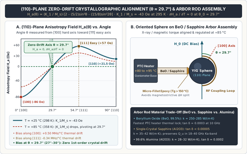
X-Ray / Magnetic Orientation, Epoxy Fillet Control, and Ceramic Arbor Rod Materials
During resonator fabrication, each polished sphere is oriented before bonding onto its cylindrical ceramic support stalk (arbor rod):
- Two-Axis Magnetic & Laue X-Ray Orientation: In a free-floating magnetic goniometer fixture (LaGrange method) or back-reflection Laue X-ray diffractometer, the
[111]easy axes and(110)plane are identified, and the precision goniometer rotates the crystal toθ = 29.7° ± 0.5°relative to the electromagnet bias axisH_0. Once mounted inside the oscillator or filter air gap, the technician rotates the arbor-rod collet slightly while sweeping temperature between+25 °Cand+85 °Con a vector network analyzer to fine-null∂f_0 / ∂T. - Low-Outgassing Micro-Fillet Epoxy Bonding: The sphere is attached to the precision-ground tip of the arbor rod (
0.20 to 0.35 mmrod diameter) using a microscopic dot of high-glass-transition (Tg > 150 °C), low-outgassing thermoset epoxy meeting NASA SP-R-0022A / ASTM E595 (Total Mass Loss TML <= 1.0%,Collected Volatile Condensable Material CVCM <= 0.10%). Adhesive fillet discipline is critical: because YIG possesses magnetostriction (λ_100 ≈ -1.4 × 10^-6,λ_111 ≈ -2.8 × 10^-6), an oversized epoxy fillet that wicks up the sides of the sphere applies anisotropic compressive stress during thermal cycling, splitting the(1,1,0)FMR line and doubling or triplingΔH. - Arbor Rod Material Selection (
BeOvs. Single-Crystal Sapphire vs. Alumina): Because the YIG sphere sits suspended inside an air gap surrounded by an RF coupling loop, the ceramic arbor rod is the only solid thermal conduction path between the sphere and the active+80 °C to +95 °CPositive Temperature Coefficient (PTC) ceramic heater mounted at the base of the stem. At the same time, the tip of the arbor rod sits directly inside the intense microwave near-field of the sphere and coupling loop, where any dielectric loss tangent (tan δ) degradesQ_rad.
The table below compares the three industry-standard ceramic arbor rod materials used across commercial and military YIG assemblies:
| Arbor Rod Material | Thermal Conductivity k (25 °C) |
Relative Permittivity ε_r (10 GHz) |
Dielectric Loss Tangent tan δ (10 GHz) |
Thermal Expansion CTE (25–300 °C) |
Primary Engineering Role & Selection Trade-Off |
|---|---|---|---|---|---|
Beryllium Oxide (BeO, 99.5% pure) |
250 – 285 W/(m·K) (exceeds aluminum metal) |
6.7 |
0.0003 – 0.0004 |
7.5 – 8.0 ppm/°C |
Fastest thermal equilibration between the +85 °C PTC heater and the YIG sphere; minimizes warm-up transient and post-step thermal drift in military EW/radar YTOs; requires toxic-dust machining safety controls |
Single-Crystal Sapphire (Al2O3, c-axis) |
35 – 42 W/(m·K) |
9.4 (⊥ c) / 11.5 (∥ c) |
< 0.00005 (ultra-low loss) |
7.0 – 8.3 ppm/°C (closest to YIG 10.4 ppm/°C) |
Lowest microwave dielectric dissipation (Q_d > 20,000); prevents dielectric radiation loading (1 / Q_rad) on tiny 0.20 mm spheres in 18–40 GHz Ka-band oscillators and narrowband preselectors; RoHS/non-toxic |
Polycrystalline Alumina (Al2O3, 99.6%) |
28 – 32 W/(m·K) |
9.8 |
0.0001 – 0.0002 |
7.2 – 8.1 ppm/°C |
Cost-effective, non-toxic standard support stalk for 2–18 GHz benchtop spectrum analyzer tracking preselectors and commercial YIG filters where moderate thermal time constants are acceptable |
Takeaway: Specify (110)-plane crystallographic orientation at θ ≈ 29.7° ± 0.5° from [100] with a minimal high-Tg epoxy fillet, pairing Beryllium Oxide (BeO) rods with fast-settling military YTO heaters and single-crystal sapphire rods with 18–40 GHz millimeter-wave resonators where tan δ < 0.00005 protects unloaded Q.
YIG Sphere Resonator Specification and Incoming Acceptance Record
When sourcing mounted YIG sphere-and-arbor sub-assemblies or auditing resonator design parameters for a custom YIG oscillator or YIG filter, record both the crystal lot properties and the mechanical mounting conditions. Leaving 4πMs, ΔH test frequency, or arbor orientation unspecified invites lot-to-lot variations in lower cutoff frequency, insertion loss, and temperature drift.
| Acceptance Field | Required Engineering Specification / Target Window | Verification Method & Reference Condition |
|---|---|---|
Crystal Composition & 4πMs Grade |
Pure Y3Fe5O12 (4πMs = 1,780 G ± 25 G) for f >= 2.0 GHz; specify exact Ga-YIG grade (1,200 G, 800 G, 600 G, or 400 G ± 15 G) for 0.45–2.0 GHz |
Vibrating-sample magnetometry (VSM) or saturation FMR cutoff check at 25 °C; verify f_min > (1/3)·γ·4πMs with Suhl coincidence margin |
Curie Temperature (Tc) |
>= 275 °C for pure YIG; >= 130 °C to 215 °C per specified Ga-YIG stoichiometry x |
Verify Tc exceeds the internal PTC resonator heater setpoint (+80 °C to +95 °C) by at least 40–50 °C |
Sphere Diameter (d_s) & Sphericity |
0.20–0.25 mm (18–40 GHz), 0.25–0.35 mm (8–18 GHz), or 0.38–0.55 mm (0.5–8 GHz); diameter tolerance ±0.005 mm, sphericity <= 0.001 mm |
Optical micrometry across orthogonal axes; confirm d_s < λ_0_min / 20 at maximum operating frequency |
Surface Roughness (Ra) & Cleanliness |
Ra <= 0.05 µm (50 nm) optical diamond/alumina tumble finish; zero surface wax, grease, or epoxy splatter on free hemisphere |
Dark-field optical inspection at 100×–200× magnification prior to cavity insertion |
Intrinsic FMR Linewidth (ΔH) & Q_u |
ΔH <= 0.25–0.35 Oe at 10 GHz, 25 °C (pure YIG) or <= 0.45–1.00 Oe (Ga-YIG); mounted unloaded Q_u >= 4,000–9,000 at X-band |
Cavity or cross-loop waveguide perturbation per Krupka et al. (2017) / ASTM A883; de-embed Q_rad |
Crystallographic Axis & Angle (θ_0) |
(110) plane aligned at θ = 29.7° (27°–30° compensated window) from [100] hard axis relative to DC bias vector H_0 (±0.5°) |
Back-reflection Laue X-ray diffraction + active swept-temperature VNA fine-nulling of ∂f_0 / ∂T over -54 °C to +85 °C |
| Arbor Rod Material & Epoxy Fillet | 99.5% BeO (k >= 250 W/m·K), c-axis Sapphire (tan δ < 0.00005), or 99.6% Alumina; low-outgassing epoxy (TML <= 1.0%, CVCM <= 0.1%, Tg > 150 °C) |
Inspect fillet meniscus height (<= 15% of sphere radius r_s); verify zero line-splitting of (1,1,0) FMR peak after 5 thermal shock cycles |
| Spurious Walker Mode Suppression | (2,1,0), (2,2,0), and (3,1,0) magnetostatic modes suppressed by >= 25–30 dB relative to main (1,1,0) resonance across full tuning span |
Swept VNA transmission (S21) and reflection (S11) trace inspection with production coupling loop geometry |
Pre-Release Engineering Checklist
- Does the lowest operating frequency drop below
2.0 GHz? If yes, replace pure YIG (4πMs = 1,780 G) with a gallium-dopedGa-YIGgrade whose(2/3)·γ·4πMscoincidence threshold and(1/3)·γ·4πMssaturation boundary match your RF input power and insertion-loss budget. - Is close-in oscillator phase noise or narrowband filter insertion loss missing target by
3 to 10 dB? Inspect the sphere under dark-field magnification for abrasive scratches, handling contamination, or wicking epoxy fillets that broadenΔHvia two-magnon surface scattering and magnetostriction. - Are spurious notches or frequency hops appearing above
18 GHz? Reduce sphere diameterd_sto0.20–0.25 mm(8–10 mils) and switch the arbor rod to single-crystal sapphire (tan δ < 0.00005) to suppress Walker magnetostatic modes and dielectric radiation loading. - Does resonant frequency drift during ambient thermal ramps despite a stable coil current source? Verify that the sphere’s
(110)plane is rotational-nulled nearθ ≈ 29.7°from[100]and that theBeOor sapphire arbor rod maintains low thermal resistance to the+85 °CPTC heater.
Takeaway: Lock down 4πMs grade, Ra <= 0.05 µm surface polish (ΔH), d_s < λ_0 / 20 diameter scaling, and θ ≈ 29.7° (110)-plane arbor orientation on the drawing before qualifying any YIG resonator assembly.
Frequently asked questions
Why must a YIG resonator be ground into a sphere instead of a disk or cube?
A sphere is the only three-dimensional geometry with identical demagnetization factors along all three principal axes (Nx = Ny = Nz = 1/3). In Kittel's ferrimagnetic resonance equation, equal demagnetization factors cancel the saturation magnetization term (4πMs) from the uniform-precession (1,1,0) resonant frequency, preventing inhomogeneous internal fields from exciting spurious magnetostatic modes and keeping tuning linear with bias field H_0.
When should an RF design specify gallium-doped Ga-YIG instead of pure YIG?
Specify gallium-doped Ga-YIG (Y3Fe5-xGaxO12, 4πMs = 400 to 1,200 Gauss) whenever the lowest operating frequency falls below 1.8 to 2.0 GHz. In pure YIG (4πMs = 1,780 Gauss), operating below 2.0 GHz drops the uniform precession mode into the half-frequency (f_0 / 2) spin-wave manifold, triggering Suhl first-order coincidence limiting and high insertion loss. Above 2.0 GHz, pure YIG is preferred for its narrower linewidth (ΔH <= 0.25–0.35 Oe) and higher Curie temperature (280 °C).
How does YIG sphere surface polish affect unloaded Q and oscillator phase noise?
Surface pits and scratches act as two-magnon scattering centers that couple energy from the uniform (1,1,0) precession mode into degenerate short-wavelength spin waves, broadening FMR linewidth ΔH. Polishing the sphere to an optical finish (Ra <= 0.05 µm) reduces ΔH below 0.25 Oe at 10 GHz, raising unloaded Q_u above 9,000. Under Leeson's phase-noise equation, doubling Q_L reduces close-in oscillator phase noise L(f_m) by 6 dB.
Why is a YIG sphere oriented at roughly 29.7 degrees on a BeO or sapphire rod?
Single-crystal YIG has negative cubic magnetocrystalline anisotropy (K_1 < 0), causing resonant frequency to shift with temperature if biased along the [100] hard axis or [111] easy axis. Rotating the bias field to θ ≈ 29.7° (27° to 30°) from [100] within the (110) crystallographic plane sets the anisotropy field H_a and its temperature derivative ∂H_a/∂T near zero. Bonding the sphere at that angle onto a high-conductivity BeO (250–285 W/m·K) or ultra-low-loss sapphire rod stabilized by a PTC heater eliminates thermal frequency drift.
Sources
- Krupka et al. (2017): Ferromagnetic resonance linewidth and unloaded Q-factor of single crystal YIG spheres — Scientific Reports Accessed October 25, 2026.
- Krupka et al. (2017): Orientation-dependent cubic anisotropy field and resonator Q equations (PDF) — Scientific Reports Accessed October 25, 2026.
- YIG Cubes and Spheres: Single-Crystal Growth, Gallium Doping, Polish & Orientation — Matesy GmbH Accessed October 25, 2026.
- Technology Description: YIG Tuned Oscillators (Resonator Coupling & Thermal Control) — Micro Lambda Wireless Accessed October 25, 2026.
- Technology Description: YIG Tuned Filters (Orthogonal Loops, Bandwidth & Suhl Limiting) — Micro Lambda Wireless Accessed October 25, 2026.
- Electromagnetic YIG Oscillators (Wide Tuning Range 0.5–40 GHz) — Micro Lambda Wireless Accessed October 25, 2026.
- Enrico Rubiola (2005): The Leeson Effect — Phase Noise in Quasilinear Oscillators — arXiv / CNRS FEMTO-ST Accessed October 25, 2026.
- Accuracy Model for Phase Noise Measurements (NIST Technical Note 860) — NIST Time and Frequency Division Accessed October 25, 2026.