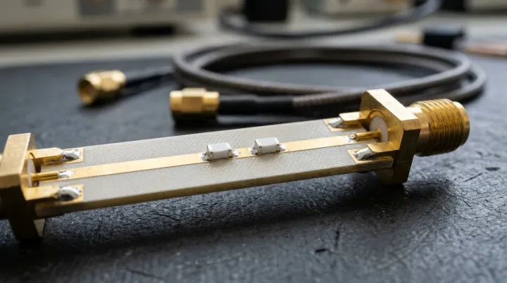
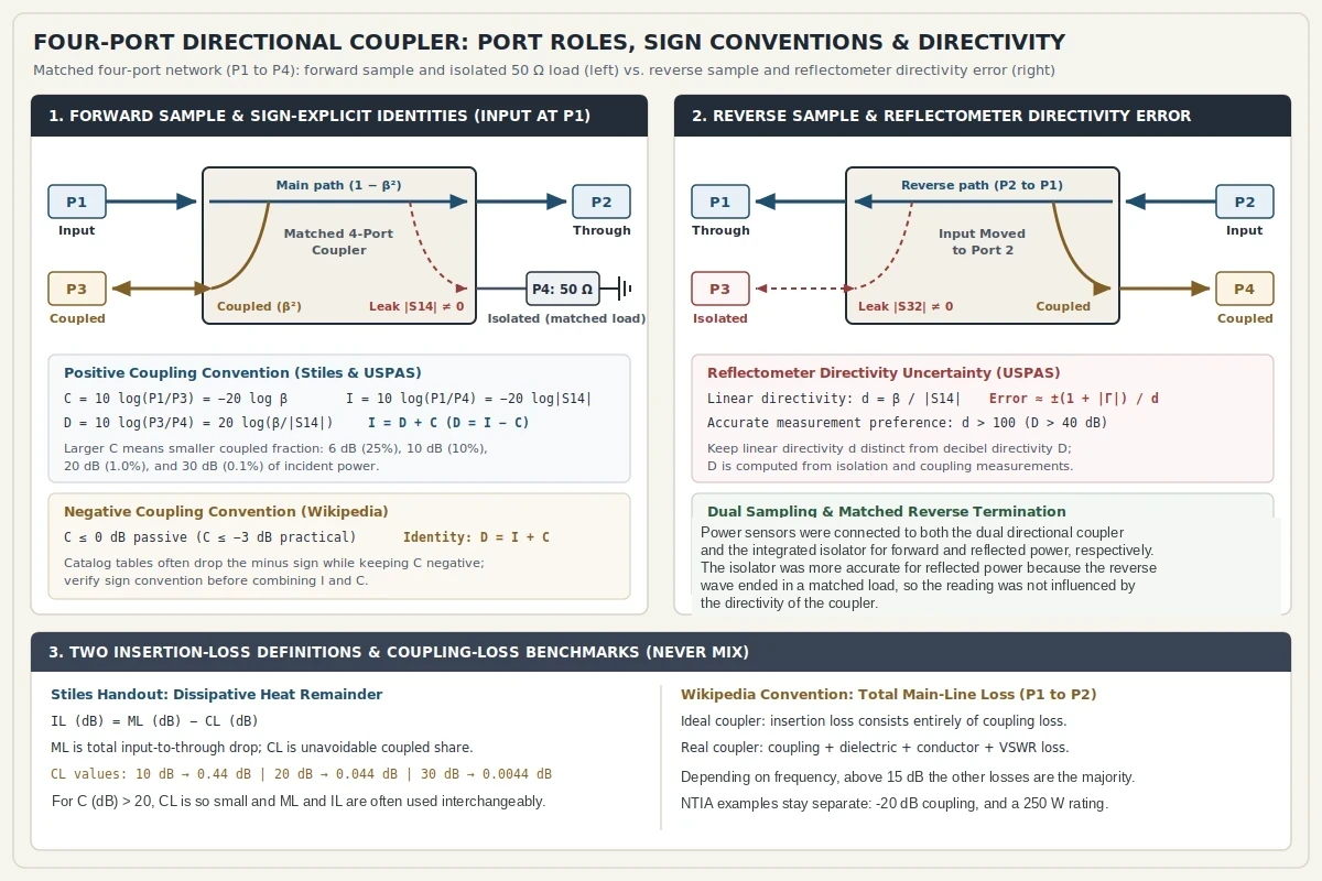
An RF directional coupler is a matched, reciprocal four-port network designed to divide power and sample power traveling in one direction down a transmission line. With matched terminations on the other ports, port 1 serves as the input port, port 2 is the through port, port 3 is the coupled port, and port 4 is the isolation port, whereas applying an input at port 2 moves the through path to port 1, couples port 4, and isolates port 3. State the coupling sign before any decibel figure: Jim Stiles’s handout and the USPAS lecture define positive coupling C = 10 log (P1/P3), and in that handout the larger the coupling value, the smaller the coupled power, while Wikipedia defines coupling factor as a negative quantity that cannot exceed 0 dB for a passive device and in practice does not exceed -3 dB, because more than that would put more power out of the coupled port than out of the transmitted port, and the minus sign is frequently dropped. Directivity rather than isolation alone sets the error on a reflected-power sample: the USPAS lecture gives an uncertainty of approximately ±(1 + |Γ|)/d, and good directivity is required for accurate measurements, preferably d > 100 (D > 40 dB).
Browse the RF and microwave components hub for passive and active selection guides organized by signal-chain job and interface parameters. Shared-antenna transmit-to-receive protection across circulators, switches, limiters, and duplexers belongs to TDD vs. FDD transceiver front-end isolation, while coupler main-line loss is only one term that RF link budget calculation and fade margin may include.
How Do Coupling, Isolation, and Directivity Relate?
Under the positive coupling used by Stiles and the USPAS lecture, C = 10 log (P1/P3) = -20 log β, isolation is I = 10 log (P1/P4) = -20 log|S14|, and directivity is D = 10 log (P3/P4) = 20 log(β / |S14|), so I = D + C and D = I - C; when Wikipedia’s coupling is the negative quantity, directivity is calculated by adding the isolation and that negative coupling, so D = I + C.
In ideal scattering-matrix analysis, a matched, lossless, reciprocal four-port becomes a directional coupler when S14 = S23 = 0, the lossless condition must be true for both the symmetric and the asymmetric solutions in order for the device to be lossless, a wave incident in port 1 couples into ports 2 and 3 but not into port 4 so ports 1 and 4 are uncoupled, and if the other ports are terminated in the characteristic impedance, all 4 ports are matched. Typical coupling coefficients in Jim Stiles’s University of Kansas handout fall in the range 0.25 > c² > 0.0001, so in that range the power out of the through port is just slightly smaller than the power incident on the input port, and the power out of the coupling port is typically a small fraction of the power incident on the input port. Under that positive coupling definition, a 6 dB coupler couples out 25% of the input power, a 10 dB coupler couples out 10%, a 20 dB coupler couples out 1.0%, and a 30 dB coupler couples out 0.1%.
An ideal directional coupler cannot be built. The input match is never perfect, so the diagonal elements of the scattering matrix are small but not zero, and the isolation port is never perfectly isolated: S41, S32, S23, and S14 are non-zero, and some small amount of power leaks out, while in reality the backward power is not zero and that nonzero backward power is what defines directivity. Isolation between the input and the isolated port can differ from isolation between the two output ports, as in Wikipedia’s example of 30 dB between ports 1 and 4 and 25 dB between ports 2 and 3, and some authors interchange ports 3 and 4, which removes the all-zero antidiagonal from the scattering matrix.
Coupling is not constant with frequency, a perfectly flat coupler theoretically cannot be built, and couplers are specified by the coupling accuracy at the frequency-band center. Directivity indicates how effective the device is in directing the coupled energy into the coupled port rather than the isolation port; Wikipedia states that directivity is not directly measurable and is calculated from the isolation and the coupling measurements; directivity is very high at the design frequency and is a more sensitive function of frequency because it depends on the cancellation of two wave components, and isolation and directivity are sensitive to frequency, but the coupling is less sensitive; see the RF engineering guides for the surrounding measurement notes.
| Parameter | Positive Coupling Convention (Stiles & USPAS) | Negative Coupling Convention (Wikipedia) |
|---|---|---|
| Coupling definition | Positive ratio C = 10 log (P1/P3) = -20 log β where larger C means smaller coupled power |
Negative quantity that cannot exceed 0 dB passively (-3 dB in practice), minus sign frequently dropped |
| Isolation definition | I = 10 log (P1/P4), equal to -20 log of the magnitude of S14 |
Input-to-isolated ratio in dB, which can differ between ports 1 and 4 and ports 2 and 3 |
| Directivity calculation | D = 10 log (P3/P4) so I = D + C and D = I - C |
Calculated from isolation and negative coupling by addition so D = I + C |
| Worked coupling benchmarks | A 6 dB coupler couples out 25% of the input power, a 10 dB coupler couples out 10%, a 20 dB coupler couples out 1.0%, and a 30 dB coupler couples out 0.1% |
Passive ceiling 0 dB; in practice coupling does not exceed -3 dB, because more than that would put more power out of the coupled port than out of the transmitted port |
| Insertion-loss naming | Avoidable absorbed-heat remainder IL (dB) = ML (dB) - CL (dB) |
Total main-line drop combining coupling, dielectric, conductor, and VSWR loss |
Why Does Insertion Loss Have Two Definitions?
In Stiles’s handout, insertion loss is the avoidable dissipative remainder IL (dB) = ML (dB) - CL (dB). Wikipedia uses insertion loss for the total main-line drop.
In Stiles’s handout, mainline loss ML is how much power the signal loses as it travels from the input to the through port, whereas coupling loss CL is the portion of that mainline loss due to coupling some of the input power into the coupling port, and conservation of energy makes this loss unavoidable: 0.44 dB for a 10 dB coupler, 0.044 dB for a 20 dB coupler, and 0.0044 dB for a 30 dB coupler. Couplers are not perfectly lossless, so there is additional loss from absorbed energy, which this handout calls heat, and insertion loss is IL (dB) = ML (dB) - CL (dB); this insertion loss is avoidable, and for couplers with C (dB) > 20 the coupling loss is so small that the mainline loss is almost entirely due to insertion loss, and the two terms are often used interchangeably.
Wikipedia instead defines insertion loss as the total main-line transmission drop: an ideal coupler’s insertion loss consists entirely of coupling loss, while a real coupler’s insertion loss consists of coupling loss, dielectric loss, conductor loss, and VSWR loss, and, depending on the frequency range, coupling loss becomes less significant above 15 dB coupling, where the other losses constitute the majority of the total loss. In the NTIA memorandum, the example of coupling factor is the amount of energy coupled to the third port, for example -20 dB, and that factor determines the insertion loss of the coupler; the memorandum says “the higher the coupling factor, the lower the insertion loss” and does not turn that sentence into a formula.
What Is the Use of a Directional Coupler in RF Systems?
A directional coupler is often used to sample a small portion of the signal power, and the coupled output can monitor frequency and power level without interrupting the main power flow, except for the power reduction of the sample.
The NTIA memorandum says directional couplers should be used after the power amplifier to monitor the output signal level, and the coupler on a propagation transmitter should be rated for the high input power, with the memorandum’s example 250 W; that output path is also discussed on the RF transmitter and receiver module page. Wikipedia’s applications include a signal sample for measurement or monitoring, feedback, combining antenna feeds, beam forming, taps for cable distribution such as cable TV, and separating transmitted and received signals on telephone lines. In Wikipedia’s two-tone combining figure, the path from port P3 to port P1 has 10 dB of loss and the path from port P2 to port P1 has 0.5 dB of loss, and isolation between the generators is what limits injection from one generator into the other.
What Are the Main Types of Directional Couplers?
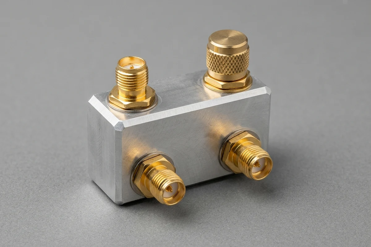
In waveguide, couplers are often single-hole, multi-hole, and branch-line couplers, and in stripline and microstrip they are often branch-line and coupled-line configurations; the Lange coupler uses interleaved paralleled lines and is used for strong couplings in the range 3 dB to 6 dB.
In waveguide, the Bethe-hole coupler is two parallel waveguides stacked with a hole between them, and it is a backward coupler. Extending that coupler with multiple holes spaced λ/4 apart widens the bandwidth, and the hole size sets the coupling of each section; in a multihole waveguide coupler the apertures between the broad walls are spaced by λ/4, forward waves through those apertures are in phase, and the backward waves are 180° out of phase and cancel, so port 4 is isolated from port 1 and port 3 is coupled; in the two-aperture design, forward waves add in phase and backward waves add out of phase if the spacing is a quarter wave or an integer multiple of that spacing; coupling through the apertures may be described by small-hole, or Bethe, coupling, and isolation and directivity are sensitive to frequency, but the coupling is less sensitive.
On planar stripline and microstrip, branch-line couplers are good for tight coupling and can be used for 3 dB hybrids, and they usually do not have as wide a bandwidth as coupled lines. Hybrids are 3 dB directional couplers with a phase difference between the output arms of either 90° or 180°, they are also useful as signal combiners, and a directional coupler designed to split power equally between two ports is called a hybrid coupler.
What Is a Dual Directional Coupler and How Does Reflectometry Work?
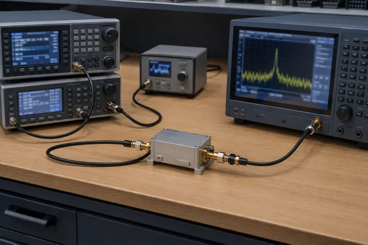
A reflectometer uses a directional coupler to separate samples of forward and reflected signals, and port 4 is usually terminated with a matched load, typically 50 ohms, which can be internal so that port is not accessible and the device effectively leaves a three-port that couples power flowing in only one direction.
In a reflectometer separating forward and reflected signals, the USPAS lecture sets β as the linear coupling factor and d = β/|S14| as the linear directivity, kept distinct from decibel directivity D. The lecture gives an uncertainty of approximately ±(1 + |Γ|)/d, and good directivity is required for accurate measurements, preferably d > 100 (D > 40 dB).
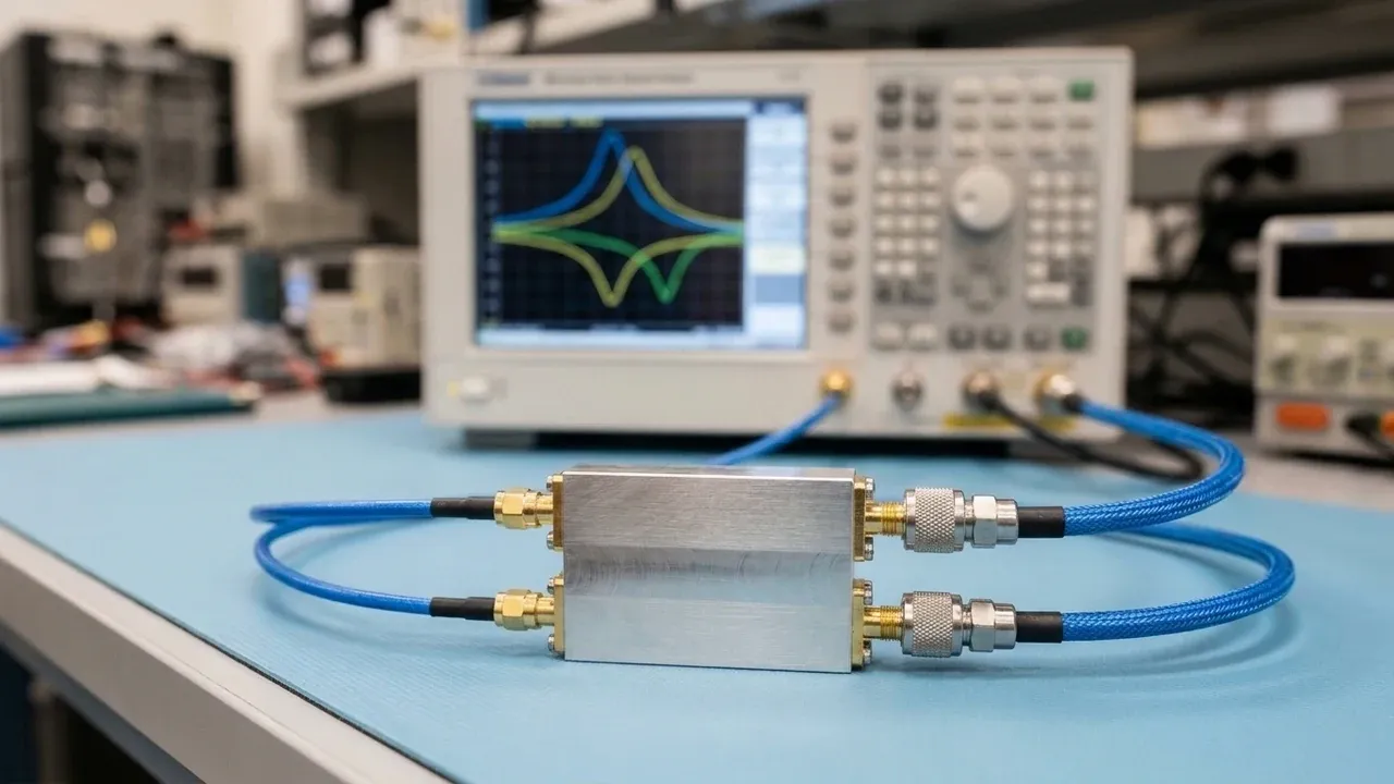
In a coaxial microwave test path documented by Oregon State University researchers, the microwave path includes a dual coaxial directional coupler; power sensors were connected to both the dual directional coupler and the integrated isolator for monitoring forward and reflected power, respectively. The integrated isolator was more accurate for monitoring the reflected power because the reverse traveling wave was terminated in a matched load, and therefore the measurements were not influenced by the directivity of the coupler.
How Does a Directional Coupler Differ from a Wilkinson Divider?
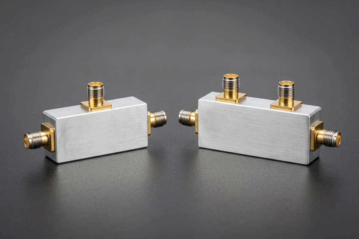
Wikipedia tends to use the name directional coupler for 4-port devices that are only loosely coupled, so only a small fraction of the input power appears at the coupled port, whereas power divider is used for tight coupling, and a typical power divider is a three-port network that divides the incident line into two equal lines each -3 dB less in power.
Equally dividing signal power looks simple, but a matched, lossless, reciprocal three-port scattering matrix produces more real equations than real unknowns, the notes say there are no solutions, and a matched, lossless, reciprocal three-port device of any kind is a physical impossibility. A simple T-junction can transmit power losslessly and the input may be matched, but the impedance into the coupled arms is not and the ports are not isolated, while a resistive divider matches all three ports, introduces a 3 dB loss in total power, and provides no isolation between ports.
The Wilkinson power divider is a 3-port device that is matched and reciprocal and is not lossless, because a divider cannot be matched, reciprocal, and lossless at the same time; Stiles places a resistor of value 2 Z0 between ports 2 and 3, the USPAS lecture connects the input and output lines by lines of √2 Zo and a resistor of 2 Zo, and Wikipedia’s own example says that for a 50 Ω system the Wilkinson lines are approximately 70 Ω. The quarter-wave transmission line sections make the Wilkinson power divider a narrow-band device, ports 2 and 3 are matched and isolated, and an ideal equal-split Wilkinson divider yields S21 = S31 = -3 dB; the resistor does not introduce loss in the power split when the two output arms are in phase, because there is no voltage across the resistor, and no loss occurs when the signals at ports 2 and 3 are in phase and have equal magnitude, while it does attenuate power coupled into the arms out of phase, and for a noise input at ports 2 and 3 half of the noise power is dissipated in the resistor.
Port and Parameter Verification Checklist
Before comparing coupler datasheets or wiring power sensors onto a bench, record the port map, coupling sign, insertion-loss convention, directivity relation, port terminations, and sampling count in one verification checklist.
| Checklist Item | Convention or Condition to Confirm | Bench & Datasheet Verification Entry |
|---|---|---|
| Port role map | Input at port 1 sets port 2 through, port 3 coupled, and port 4 isolated unless an author interchanges ports 3 and 4 | Record input, through, coupled, and isolated connector labels for the active wave direction |
| Coupling sign | Positive C = 10 log (P1/P3) versus negative passive factor (0 dB passive limit, -3 dB in practice) where the minus sign is frequently dropped |
Write + or - convention explicitly ahead of the nominal coupling decibel figure |
| Insertion-loss name | Stiles absorbed-heat remainder IL (dB) = ML (dB) - CL (dB) versus Wikipedia total main-line loss |
State whether quoted loss excludes or includes unavoidable coupling loss CL |
| Directivity vs. isolation | Calculated D = I - C (positive C) or D = I + C (negative C); d > 100 (D > 40 dB) preferred for reflectometry |
Compute D from I and C rather than treating isolation I as directivity |
| Port termination and power rating | Port 4 terminated in a matched characteristic-impedance load (typically 50 ohms, internal or external) and coupler rated for transmitter input power (such as NTIA’s 250 W example) |
Verify whether port 4 is internally terminated or attach a matched load, and check input power rating |
| Sampled directions | Effective three-port single-direction coupler with terminated port 4 versus a dual coaxial directional coupler and an integrated isolator, with sensors monitoring forward and reflected power, respectively | Select one-direction sampling after a power amplifier, or forward and reflected samples for a reflectometer |
Sources
- Jim Stiles, The Directional Coupler, University of Kansas lecture handout.
- Jim Stiles, Properties of Dividers and Couplers, University of Kansas lecture handout.
- Jim Stiles, The Wilkinson Power Divider, University of Kansas lecture handout.
- Jose E. Schutt-Aine, Directional Couplers, University of Illinois lecture notes.
- U.S. Particle Accelerator School, Microwave Measurements: Power Dividers and Directional Couplers, Fermi National Accelerator Laboratory lecture notes.
- Power dividers and directional couplers, Wikipedia.
- Wilkinson power divider, Wikipedia.
- National Telecommunications and Information Administration, Propagation Transmitter Directional Coupler Guidance, U.S. Department of Commerce technical memorandum.
- Kupp et al., Journal of Vacuum Science and Technology A, Oregon State University.